3304 DIRECT INJECTION VEHICULAR ENGINE
TM 5-3805-258-24-1
WITH SCROLL FUEL SYSTEM
SPECIFICATIONS
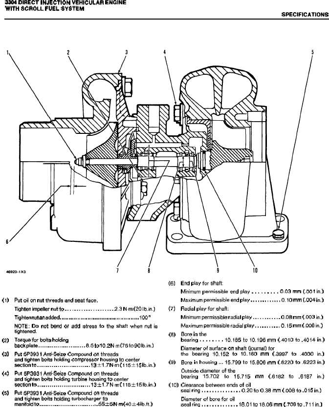
TURBOCHARGER
(AiResearch T04B81)
(1)
(2)
(3)
(4)
(5)
Put oil on nut threada and seat face.
Tighten impeller nut to . . . . . . . . . . . . . . . . . . . . . 2.3 N.m (20 Ib.in.)
Tighten nut an added . . . . . . . . . . . . . . . . . . . . . . . . . . . . . . . . . . . . . . . . . . . . . . 100°
NOTE: Do not bend or add stress to the shaft when nut is
tightenad.
Torque for bolts holding
back plate . . . . . . . . . . . . . . . . . . . . . . . . . 8.5 to 10,2 Nm (75 to 90 Ib.in.)
Put 5P3931 Anti-seize Compound on threads
and tighten bolts holding compressor housing to center
section to . . . . . . . . . . . . . . . . . . . . . . . . . . 13 * 1.7 N.m (115 t 15 Ib. in.)
Put 5P3931 Anti-Seize Compound on threads
and tighten bolts holding turbine housing to center
section to . . . . . . . . . . . . . . . . . . . . . . . . . . 13 ~ 1.7 Nm (115 t 15 Ib, in.)
Put 5P3931 Anti-Seize Compound on threads
and tighten bolts holding turbocharger to
manifold to . . . . . . . . . . . . . . . . . . . . . . . . . . . . . . . 55 t 5 N.m (40 * 4 Ib.ft.)
(6)
(7)
(8)
(9)
(lo)
End play for shaft:
Minimum permissible end play . . . . . . . . . 0.03 mm (.001 in.)
Maximum permissible end play . . . . . . . . . . . . . 0.10 mm (.004 in.)
Radial play for shaft:
Minimum permissible radial play . . . . . . . . . . . . 0.08 mm (.003 in.)
Maximum permissible radial play . . . . . . . . . . . 0.15 mm (.006 in.)
Bore in the
bearing . . . . . . . . 10.185 to 10.196 mm (.4010 to .4014 in.)
Diameter of surface on shaft (journal) for
the
bearing 10.152 to 10.160 mm (.3997 to .4000 in.)
Bore in housing ,.. 15.799 to 15.806 mm (.6220 to .6223 in.)
Outside diameter of the
bearing
15.702
to
15.715
mm
(.6182
to
.6187
in.)
Clearance between ends of oil
seal ring . . . . . . . . . . . . . . . 0.20 to 0.38 mm (.008 to .015 in.)
Diameter of bore for oil
seal ring . . . . . . . . . . . . . . 18.01 to 18.06 mm (.709 to .711 in.)
2-11