TM 5-3805-258-24-1
950B POWER TRAIN
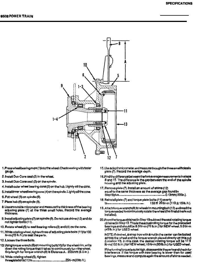
ADJUSTMENT OF THE WHEEL BEARINGS
1. Press wheel bearing cups(1) into the wheel. Check seating with feeler
gauge.
2. Install Duo-Cone seal (2) in the wheel.
3. Install Duo-Cone seal (2) on the spindle.
4. Install outer wheel bearing ccme (3) on the hub. Lightly oil the cone.
5. Install inner whsel bearing cone(4) on the spindle. Lightly oil the cone.
6. Put wheel (5) on spindle (9).
7. Place hub (6) on spindle (9).
8. Uee an outside micrometer and meaaure the thickness of the bearing
adjusting plate (7) at the three small Mea. Record the average
thckness.
9. Install adjusting plate (7) on sp4rrdle (9). Do not use shims (12) and do
not tighten bolts (1 1).
10. Rotate wheel (5) to seat bearing rollers (3) and (4) on the cone.
11. While rotating wheel, tighten three of adjusting plate bolts(11) to 100
N.m (75 Ib.ft.) to seat the parts.
12. Loosen the three bolts.
13. Using torque wrench (6) on mounting bolt (10) for the wheel rim, write
down the rolling torque that it takes to continuously turn the wheel.
Grip length for torque wrench (8) is Oistance A .203 mm (6.0 in.).
14. While rotating wheel (5), tighten
three plate bolts (11) to . . . . . . . . . . . . . . . . . . . . . . . . . . . . . . . . . . . . . 25 N.m (20 Ib,ft.).
15. Use a depth micrometer and measure through the three small holes in
plate (7). Record the average depth.
16. Find the difference between the two average measurements in steps
8 and 15. The difference is the gap between the end of the spindle
housing and the adjusting plate.
17. Remove plate (7), Install an amount of shims (12)
equal to the same thickness as the average gap found in
Step 16 plus . . . . . . . . . . . . . . . . . . . . . . . . . . . . . . . . . . . . . . . . . . . . . . . . . . . . 0.13 mm (.005 in.).
18. Reinstall plate (7) and torque plate bolts (11 ) evenly
to . . . . . . . . . . . . . . . . . . . . . . . . . . . . . . . . . . . . . . . . . . . . . . . .
150 *20 Nom (110 * 15 Ib.ft.).
19. Attach torque wrench (8) to wheel rim mounting bolt (10) and read the
torque needed to continuously rotate the wheel (the final drive is not
installed).
20. From the torque obtained in Step 19 subtrect the seal rotating torque
obtained in Step 13. This ia the actual rolling torque for the preloaded
bearings and should be 8.0 N-m (70 Ib.in.) for NEW wheel; 5.0 Nom
(45 Ib.in.) for USED wheel.
NOTE: If desired, a strap iron with a nut in the center can be bolted
across the wheel and the torque wrench placed directly on this nut
(Location 13). In this case, the desired rotating torque will be 17.5
N-m (155 Ib.in.) for NEW whee~ 10 N*m (90 Ib.in.) for USED wheel.
If the turning torque is quite high, disassemble the parta and check for
interference. If the torque with new bearing is lower than for used
bearings, measure and compute again the amount of shims needed.
2-45/ 2-46(blank)