TM 5-3805-258-24-1
95t)B POWER TRAIN
SPECIFICATIONS
11.
12.
13,
Differential and Bevel Gear
(Cont.)
ILLUSTRATION A
Measure in the backlash between the ring
gear and pinion again. The backlash must
still be . . . . . . . . . . . . . . . . . . . . .
0.20 to .43 mm (.008 to .017 in.)
If backlash is too much, loosen adjustment ring (1) and
tighten adjustment ring (14) the same amount.
If backlash is not enough, loosen adjustment ring (14) and
tighten adjustment ring (1) the same amount.
NOTE: The differential preload will be kept only if one adjustment
ring is loosened and the other adjustment ring is tightened the
same amount.
14, After the backlash and preload adjustments have been made,
the tooth contact between pinion (10) and ring gear (12) must
then be checked. Do the procedure that follows:
a.
b.
c.
Put a small amount of Prussian blue, red lead or paint on
the teeth of ring gear (12).
Turn pinion (10) in both directions.
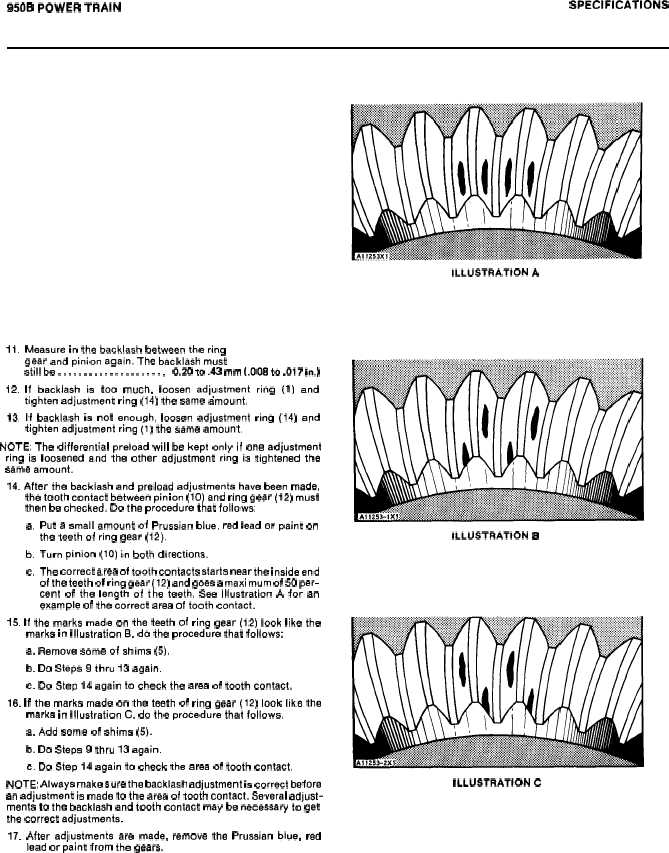
The correct area of tooth contacts starts near the inside end
of the teeth of ring gear (12) and goes a maximum of 50 per-
cent of the length of the teeth. See Illustration A for an
example of the correct area of tooth contact.
15. If the marks made on the teeth of ring gear (12) look like the
marks in Illustration B, do the procedure that follows:
a. Remove some of shims (5).
b. Do Steps 9 thru 13 again.
c. Do Step 14 again to check the area of tooth contact.
16. If the marks made on the teeth of ring gear (12) look like the
marks in Illustration C, do the procedure that follows.
a. Add some of shims (5).
b. Do Steps 9 thru 13 again.
c. Do Step 14 again to check the area of tooth contact.
NOTE: Always make sure the backlash adjustment is correct before
an adjustment is made to the area of tooth contact. Several adjust-
ments to the backlash and tooth contact may be necessary to get
the correct adjustments.
17. After adjustments are made, remove the Prussian blue, red
lead or paint from the gears.
ILLUSTRATION B
ILLUSTRATION C
2-42


