F U E L S Y S T E M
TM 5-3805-258-24-1
S Y S T E M S
O P E R A T I O N
FUEL FLOW
FUEL SYSTEM
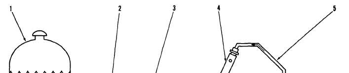
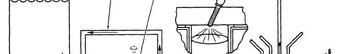
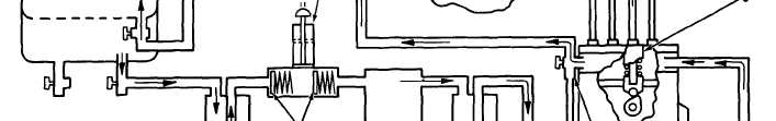
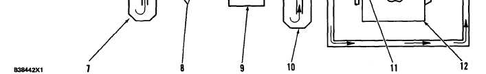
FUEL SYSTEM SCHEMATIC
1. Fuel tank. 2. Fuel return line. 3. Priming pump. 4. Fuel injection nozzle. 5. Fuel injection line. 6. Fuel injection pump. 7. Primary
fuel filter. 8. Check valves. 9. Fuel transfer pump. 10. Secondary fuel filter. 11. Constant bleed valve. 12. Fuel injection pump
h o u s i n g .
Fuel is pulled from fuel tank (1) through primary
fuel filter (7) and check valves (8) by fuel transfer
pump (9). From the fuel transfer pump the fuel is
pushed through secondary fuel filter (10) and to the
fuel manifold in fuel injection pump housing (12). A
bypass valve in the fuel transfer pump keeps the fuel
pressure in the system at 170 to 280 kPa (25 to 40
psi). Constant bleed valve (11) lets a constant flow of
fuel go through fuel return line (2) back to fuel tank
(1). The constant bleed valve returns approximately
34 liters (9 gal.) per hour of fuel and air to the fuel
tank. This helps keep the fuel cool and free of air.
There is also a manual bleed valve that can be used
when the fuel priming pump is used to remove air
from the system. Fuel injection pump (6) gets fuel
from the fuel manifold and pushes fuel at very high
pressure through fuel line (5) to fuel injection nozzle
(4). The fuel injection nozzle has very small holes in
the tip that change the flow of fuel to a very fine
spray that gives good fuel combustion in the cylinder.
FUEL INJECTION PUMP
The fuel injection pump increases the pressure of
the fuel and sends an exact amount of fuel to the fuel
injection nozzle. There is one fuel injection pump for
each cylinder in the engine.
The fuel injection pump is moved by cam (14) of
the fuel pump camshaft. When the camshaft turns,
the cam raises lifter (11) and pump plunger (6) to the
top of the stroke. The pump plunger always makes a
full stroke. As the camshaft turns farther, spring (8)
returns the pump plunger and lifter to the bottom of
the stroke.
3-3