F U E L S Y S T E M
TM 5-3805-258-24-1
S Y S T E M S
O P E R A T I O N
The air fuel ratio control limits the amount of
fuel to the cylinders during an increase of engine
speed (acceleration) to reduce exhaust smoke.
Stem (6) moves lever (11) which will restrict the
movement of the fuel rack in the FUEL ON direc-
tion only.
With the engine stopped, stem (6) is in the fully
extended position. The movement of the fuel rack
and lever (11) is not restricted by stem (6). This
gives maximum fuel to the engine for easier starts.
After the engine is started, engine oil flows
through oil inlet (5) into pressure oil chamber (10).
From oil chamber (10) oil flows through oil pas-
sage (9) into internal valve (3) and out oil drain
passages in stem (6).
Stem (6) will not move until inlet manifold pres-
sure increases enough to move internal valve (3).
A line connects the inlet manifold with inlet air
chamber (1) of the air fuel ratio control.
When inlet manifold pressure increases, it causes
diaphragm assembly (2) to move towards the right.
This also causes internal valve (3) to move to the
right. When internal valve (3) moves to the right,
it closes oil passage (9).
When oil passage (9) is closed, oil pressure in-
creases in oil chamber (10). Oil pressure moves
piston (8) and stem (6) to the left and into the
operating position. The air fuel ratio control will
remain in the operating position until the engine
is shut off.
When the governor control is moved to increase
fuel to the engine, stem (6) limits the movement
of lever (11) in the FUEL ON direction. The oil
in oil chamber (10) acts as a restriction to the move-
ment of stem (6) until inlet air pressure increases.
As the inlet air pressure increases, diaphragm
assembly (2) and internal valve (3) move to the
right. The internal valve opens oil passage (9),
and oil in oil chamber (10) goes to oil drain pas-
sage (4). With the oil pressure reduced behind
piston (8), spring (7) moves the piston and stem
(6) to the right. Piston and stem (8 and 6) will move
until oil passage (9) is closed by internal valve (3).
Lever (11) can now move to let the fuel rack go to
the full fuel position. The air fuel ratio control is
designed to restrict the fuel until the air pressure
in the inlet manifold is high enough for complete
combustion. It prevents large amounts of exhaust
smoke caused by an air-fuel mixture with too much
fuel.
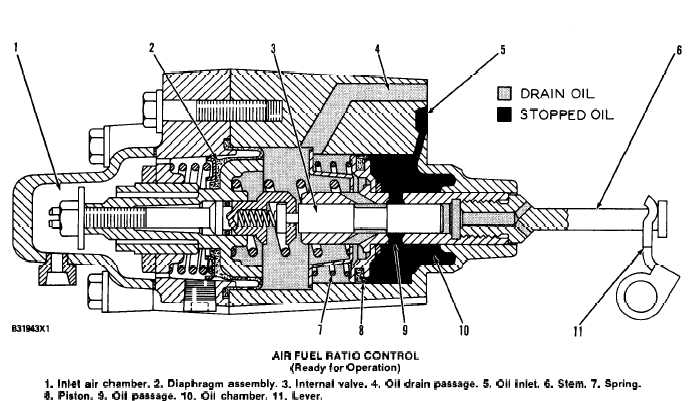
AIR FUEL RATIO CONTROL
(Ready for Operation)
1. Inlet air chamber. 2. Diaphragm assembly. 3. Internal valve. 4. Oil drain passage. 5. Oil inlet. 6. Stem. 7. Spring.
8. Piston. 9. Oil passage. 10. Oil chamber. 11. Lever.
3-10.1/3-10.2 (blank)