E N G I N E
F U E L S Y S T EM
TM 5-3805-258-24-1
S Y S T E M S
O P E R A T I O N
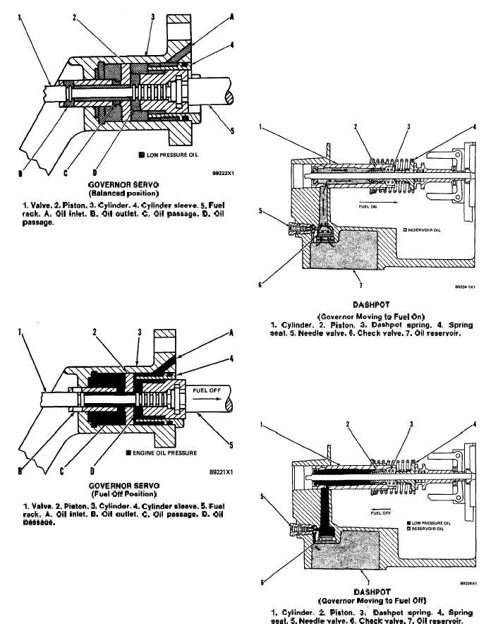
GOVERNOR SERVO
(Balanced position)
I. Valve. 2. Piston. 3. Cylinder. 4. Cylinder sleeve. 5. Fuel
rack. A. Oil inlet. B. Oil outlet. C. Oil passage. D. Oil
passage.
When the governor spring and flyweight forces are
balanced and the engine speed is constant, valve (1)
stops moving. Pressure oil from oil inlet (A) pushes
piston (2) until oil passages (C and D) are opened.
Oil now flows through oil passage (D) along valve (1)
and out through oil outlet (B). With no oil pressure
on the piston, the piston and fuel rack (5) stop
moving.
GOVERNOR SERVO
(Fuel Off Position)
1. Valve. 2. Ptston. 3. Cylinder. 4. Cytinder sleeve. 5. Fuel
rack. A. Oil inlet. B. Oil outlet. C. Oil pasaage. D. Oil
oaaaaae.
When the governor moves in the FUEL OFF dir-
ection, valve (1) moves to the right. The valve closes
oil outlet (B) and opens oil passage (D). Pressure oil
from oil inlet (A) is now on both sides of piston (2).
The area of the piston is greater on the left side than
on the right side of the piston. The force of the oil is
also greater on the left side of the piston and moves
the piston and fuel rack (5) to the right.
Dashpot
The dashpot helps give the governor better speed
control when there are sudden speed and load
changes. The dashpot has cylinder (1), piston (2),
dashpot spring (3), needle valve (5) and check valve
(6). Piston (2) and spring seat (4) are fastened to
dashpot spring (3).
DASHPOT
(Governor Moving to Fuel On)
1. Cylinder. 2. Piston. 3. Dashpot spring. 4. Spring
seat. 5. Needle valve. 6. Check valve. 7. Oil reservoir.
When the governor moves toward FUEL ON,
spring seat (4) and piston (2) move to the right. This
movement pulls oil from oil reservoir (7) through
check valve (6) and into cylinder (1).
DASHPOT
(Govarnor Moving to Fuel Off)
1. Cylinder. 2. Piston. 3.’ Dashpot spring. 4. Spring
seat. 5. Needle valva. 6. Check valve. 7. Oil reservoir.
3-9


