E N G I N E
C O O L I N G
S Y S T E M
TM 5-3805-258-24-1
S Y S T E M S O P E R A T I O N
COOLING SYSTEM
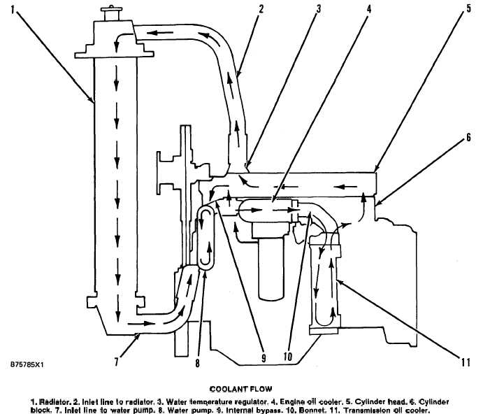
COOLANT FLOW
1. Radiator. 2. iniet line to radiator. 3. Water temperature regulator. 4. Engine oii cooier. 5. Cyiinder head. 6. Cyiinder
block. 7. Inlat line to water pump. 8. Water pum”p. 9. inter;al bypass. 10. Bonnet. 11. Tran8misaion oil cooler.
COOLANT FLOW
Water pump (8) is on the left front side of the
engine. It is gear driven by the timing gears. Coolant
from the bottom of radiator (1) goes to water pump
inlet (7). The rotation of the impeller in water pump
(8) pushes the coolant through the system.
When an engine does not have a transmission oil
cooler, all of the coolant flow from water pump (8)
goes through engine oil cooler (4). Bonnet (10) on
the outlet side of engine oil cooler (4) connects to
the side of cylinder block (6).
When an engine has a transmission oil cooler a
different bonnet (10) is on engine oil cooler (4). This
bonnet (10) sends the coolant flow through the
transmission oil cooler (11) which is for the torque
converter. The flow goes through one side on the
3-15
way into cooler (11). At the bottom of cooler (11)
the flow turns and goes back up through the other
side and into bonnet (10) again. Then bonnet (10)
sends the coolant into cylinder block (6).
Inside cylinder block (6) the coolant goes around
the cylinder liners and up through the water direc-
tors into cylinder head (5). The water directors send
the flow of coolant around the valves and the pas-
sages for exhaust gases in cylinder head (5). The
coolant goes to the front of cylinder head (5). Here
water temperature regulator (3) controls the direc-
tion of the flow. If the coolant temperature is less
than normal for engine operation, water tempera-
ture regulator (3) is closed. The only way for the
coolant to get out of cylinder head (5) is through
internal bypass (9). The coolant from this line goes
into water pump (8) which pushes it through the