TM 5-3805-258-24-1
S Y S T E M S O P E R A T I ON
E N G I NE
AIR INLET AND EXHAUST SYSTEM
AIR INLET AND EXHAUST SYSTEM
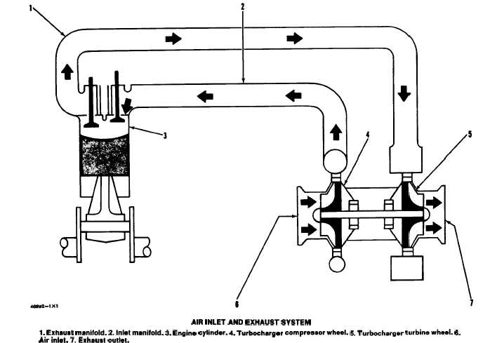
AIR INLET AND EXHAUST SYSTEM
l. Exhaust manifold. 2.hrlatmanifold. 3. Engine cylinder. 4. Turbocharger compraaaorwhaeL 5. Turbocharger turbinawhaeL 6.
Air inlet. 7. Exhauat outlet.
The air inlet and exhaust system components are:
TURBOCHARGER
air cleaner, inlet manifold, cylinder head, valves and
valve system components, exhaust manifold, and
The turbocharger is installed on the exhaust mani-
turbocharger.
fold. All the exhaust gases from the engine go
Clean inlet air from the air cleaner is pulled
through the turbocharger.
through the air inlet (6) of the turbocharger by the
The exhaust gases enter exhaust inlet (7) and go
turning compressor wheel (4). The compressor wheel
through the blades of turbine wheel (4), causing
causes a compression of the air. The air then goes to
the turbine wheel and compressor wheel (2) to
the inlet manifold (2) of the engine. When the intake
turn.
valves open, the air goes into the engine cylinder (3)
and is mixed with the fuel for combustion. When the
When the compressor wheel turns, it pulls fil-
exhaust valves open, the exhaust gases go out of the
tered air from the air cleaners through air inlet (1).
engine cylinder and into the exhaust manifold (1).
The air is put in compression by action of the com-
From the exhaust manifold, the exhaust gases go
pressor wheel and is pushed to the inlet manifold
through the blades of the turbine wheel (5). This
of the engine.
causes the turbine wheel and compressor wheel to
When engine load increases, more fuel is in-
turn. The exhaust gases then go out the exhaust
outlet (7) of the turbocharger.
jetted into the engine cylinders. The volume of
exhaust gas increases which causes the turbo-
3-11