TM 5-3805-258-24-1
P O W E R T R A I N
T R A N S M I S S I O N
H Y D R A U L I C
S Y S T EM
Outlet oil from the converter goes to relief valve
(13) for converter outlet. The relief valve (13) keeps
the pressure inside the converter at approximately
415 kpa (60 psi). From the outlet relief valve, the oil
goes through line (6) to oil cooler (12).
After going through the cooler, the oil at a lower
temperature, goes through outlet line (14) to the
transmission planetary. This oil is for lubrication of
the transmission.
The oil from flywheel housing (7) goes through
return line (15) to the main reservoir at the bottom of
case (11).
OIL PUMP
L O C A T I O N O F O I L P U M P
The oil pump is a single-section gear-type mount-
ed between the hydraulic implement pump and the
housing assembly (torque converter housing).
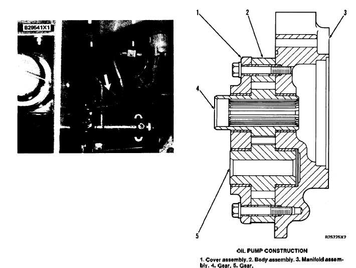
The main components of the oil pump are: body
assembly (2), cover assembly (1), manifold assembly
(3), gear (4) and gear (5).
Drive gear (4) is connected by splines to the pump
drive. The hydraulic implement pump is driven by
drive gear (4).
S Y S T E M S O P E R A T I O N
In operation, oil comes from the reservoir in the
output transfer gear case, through the magnetic
screen to an opening in manifold assembly (3). The
oil fills the spaces between the teeth of gears (4), and
(5) and body (2). As the gears turn, oil is pushed
from body (2). The oil goes through another passage
in manifold assembly (3) to an oil line. The oil then
goes to the filter.
When the engine is not running, air is present in
the pump. When the engine is started, a line on the
outlet side of the pump lets the air go from the pump.
This prevents air from getting into the system. After
all air is out of the pump, an orifice in the line lets a
specific amount of oil go to the relief valve for con-
verter outlet.
OIL PUMP CONSTRUCTION
1. Cover asaembly. 2. Body aasembly. 3. Manifold aaaem-
bly. 4. Gear. 5. Gear.
3-27