TM 5-3805-258-24-1
P O W E R T R A IN
T O R Q U E C O N V E R T E R
S Y S T E M S O P E R A T I O N
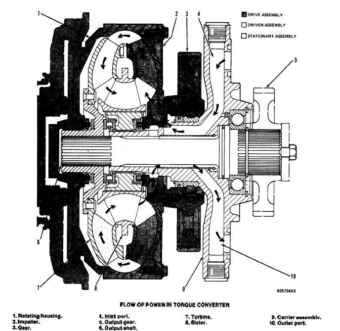
FLOW OF POWER IN TORQUE CONVERTER
I. Rotating housing.
4.lrrlet port.
7. Turbine.
9. Carrier assemblv.
2. Impeller.
S. Output gear.
3. Gear.
8. Stator.
10. Outlet port.
6. Output shaft.
Oil from the transmission hydraulic controls
The oil goes through a passage in carrier (9) to
enters the torque converter through inlet port (4) in
outlet port (10). From outlet port (10), oil is directed
carrier (9). Oil is directed to the inlet port by a
to the converter outlet relief valve. All the oil from
passage in the converter housing. From inlet port (4),
the outlet relief valve goes to the oil cooler, where the
the oil goes through a passage in the hub. As impeller
temperature of the oil is lowered. From the oil cooler,
(2) rotates, it acts as a pump to direct oil to turbine
the oil is then sent to the transmission where it is used
(7). The turbine is bolted to a hub, which is connect-
to cool and lubricate the internal components.
ed to output shaft (6) by splines. The turbine directs
oil to stator (8), which is held stationary. The stator
is connected to carrier (9) by splines. Carrier (9) is
bolted to the torque converter housing.
3-22


