TM 5-3805-258-24-1
P O W E R T R A I N
S Y S T E M S O P E R A T I O N
TRANSMISSION
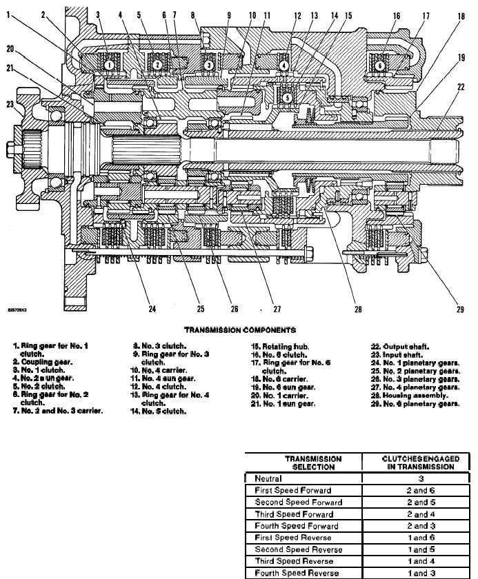
TRANSMISSION COMPONENTS
1. Ring gear for No. 1
clutch.
2. Coupling geer.
3. No. 1 oiutch.
4. No. 2 l un gear.
5. No. 2 ciutch.
& Ring gear for No. 2
ciutch.
7. No. 2 and No, 3 carrier.
& No. 3 clutch.
9. Ring gear for No. 3
ciutch.
10. No. 4 oarriar.
11. No. 4 aun gaar.
12. No. 4 clutch,
13. Ring gear for No. 4
clutch.
14. No. 5 clutch.
The transmission has six hydraulically activated
clutches that give four speeds FORWARD and four
speeds REVERSE. Speed and direction are both
manually selected.
The transmission is fastened between the torque
converter cover and the case for the output transfer
gears. Input power to the transmission comes from
the torque converter.
A speed clutch and a direction clutch must both be
engaged, in that order, to send power through the
transmission. The chart gives the combination of the
clutches engaged for each FORWARD and RE-
VERSE speeds.
15. Rotating hub.
16. No. 6 clutch.
17. Ring gear for No.
clutch.
18. No. 6 carrier.
19. No. 6 eun gear.
20. No. 1 carrier.
21. No. 1 sun gear.
22. Output shaft.
23. input ehaft.
6
24. No. 1 planetary gears.
25. No. 2 pianatary geare.
25. No. 3 planetary geare.
27. No. 4 pianetary gears.
28. Housing aseembiy.
26. No. 6 pianetary geare.
I
TRANSMISSION
I
CLUTCHES ENGAGED
SELECTION
iN TRANSMISSION
I
I
Neutral
I
3
I
First Speed Forward
2 and 6
Second Speed Forward
2 and 5
Third Speed Forward
2 and 4
Fourth Speed Forward
2 and 3
First Speed Reverse
1 and 6
Second Speed Reverse
1 and 5
Third Speed Reverse
1 and 4
Fourth Speed Reverse
1 and 3
3-30