P O W E R T R A IN
TM 5-3805-258-24-1
T O R Q U E C O N V E R T E R H Y D R A U L I C S Y S T E M
S Y S T E M S O P E R A T I O N
Two control valves make up the hydraulic system
for the torque converter. These valves are the inlet
pressure valve for the torque converter and the relief
valve for converter outlet.
RATlO VALVE FOR THE
TORQUE CONVERTER
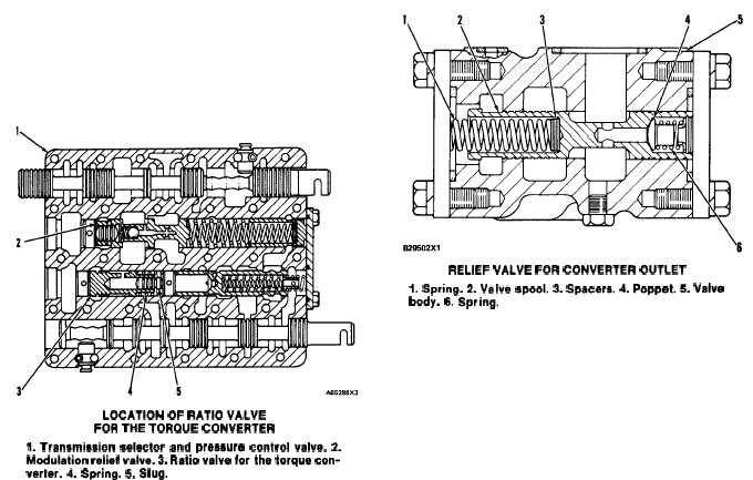
LOCATION OF RATlO VALVE
FOR THE TORQUE CONVERTER
1. Transmission selector and pressure control valve. 2.
Modulation relief valve. 3. Ratio valve forthe torque con-
verter. 4. Spring. 5. Slug.
The ratio valve for the torque converter controls
the maximum pressure to the converter. The main
purpose of the ratio valve is to prevent damage to
converter components when the engine is started and
the oil is cold. It limits the maximum pressure to the
converter to approximately 965 kPa (140 psi). This
pressure is not adjustable.
RELIEF VALVE FOR CONVERTER OUTLET
RELIEF VALVE FOR CONVERTER OUTLET
1. Spring. 2. Valve spool. 3. Spacers. 4. Poppet. 5. Valve
body. 6. Spring.
The relief valve for converter outlet controls the
maximum pressure in the torque converter. When
the pressure in the converter is approximately 415
kPa (60 psi), spool (2) moves against the force of
spring (1) to let the extra oil go to the oil cooler.
The outlet relief valve is mounted to the right side
of the converter cover.
Spacers (3) are used to make an adjustment to the
opening pressure of the valve.
3-25