P O W E R T R A I N
T R A N S M I S S I O N
H Y D R A U L I C
C O N T R O LS
TM 5-3805-258-24-1
S Y S T E M S O P E R A T I O N
Engine Running
(Neutral to First Speed Forward)
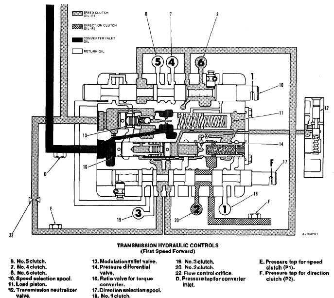
TRANSMISSION HYDRAULIC CONTROLS
(First Speed Forward)
6. No. 5 clutch.
13. Modulation relief valve.
7. No. 4 clutch.
14. Pressure differential
6. No. 6 clutch.
valve.
10. Speed selection spool.
16. Ratio valve for torque
11. Load piston.
convertar.
12. Transmission neutralizer
17. Direction selection spool.
valve.
16. No. 1 clutch.
When the transmission selection lever is moved to
FIRST SPEED FORWARD, speed selection spool
(10) and direction selection spool (17) are in the
positions shown in the schematic.
The position of direction selection spool (17) opens
a passage to No. 2 clutch (20). It also opens passages
from No. 3 clutch (19) and No. 1 clutch (18) to the
reservoir.
The position of speed selection spool (10) opens a
passage from No. 6 clutch (8) to pump oil. It also
opens No. 4 clutch (7) and No. 5 clutch (6) to the
reservoir.
19. No. 3 clutch.
E. Pressure tap for speed
20. No. 2 clutch.
clutch (Pi).
22. Flow control orifice.
F. Pressure tap for direction
D. Pressure tap for converter
clutch (P2).
inlet.
When the shift to FIRST SPEED FORWARD is
made, the No. 3 clutch is opened to the reservoir. The
pressure in the system decreases. Springs move mo-
dulation relief valve (13) toward the left. Springs
move pressure differential valve (14) toward the left
until the large orifice at the left end of valve (14) is
closed to pump oil by the valve body.
As the pressure differential valve moves toward
the left, the chamber behind load piston (11) opens to
the reservoir. This lets the springs move the load
piston to the right. The pressure differential valve is
in a position to let the pressure increase in the speed
clutch circuit.
The speed clutch oil starts to fill No. 6 clutch (8).
3-45