P O W E R T R A IN
T R A N S M I S S I O N
H Y D R A U L I C
C O N T R O L S
TM 5-3805-258-24-1
S Y S T E M S
O P E R A T I O N
OPERATION
Starting the Engine
(Transmission in Neutral)
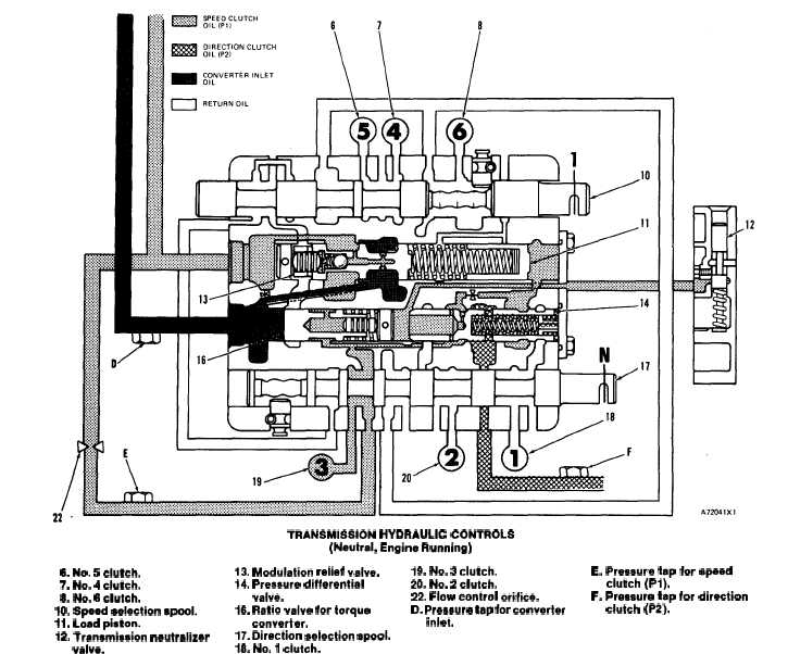
TRANSMISSION HYDRAULIC CONTROLS
(Neutral, Engine Running)
& No. 5 clutch.
13. Modulation relief velve.
19. No. 3 clutch.
E. Pressure tap for spaed
7. No. 4 clutch.
14. Pressure differential
20. No. 2 clutch.
8. No. 6 clutch.
clutch (Pi).
valve.
22. Flow control orifica.
F. Praasure tap for diraction
10. Spead selection spool.
16. Ratio valva for torqua
D. Praaaure tap for convarter
clutch (P2).
11. Load piston.
convartar.
inlet.
12. Tranamiaaion neutralizer
17. Diraction selection spool.
valva.
18. No. 1 clutch.
When the engine is started, oil pump (9) pulls oil
(17) also opens direction clutches (18) and (20) to
from reservoir (21) through magnetic screen (15).
the reservoir.
The pump sends the oil through filter (1) to the
selector and pressure control valve group, which is
Oil, from the pump, goes through flow control
part of the transmission hydraulic controls.
orifice (22) to No. 3 clutch (19), ratio valve (16) for
When the transmission selection lever is in NEU-
the torque converter and pressure differential valve
TRAL, direction selection spool (17) is in the posi-
(14).
tion shown in the schematic.
The oil to ratio valve ( 16) for the torque converter,
The position of direction selection spool (17) opens
goes through an orifice in the valve spool and fills the
No. 3 clutch (19) to pump oil and opens the right end
slug chamber.
of pressure differential valve (14) to the reservoir.
The oil to pressure differential valve (14) goes
Speed clutches (6), (7) and (8) are opened to the
through a small orifice in the valve spool and starts to
reservoir. The position of direction selection spool
fill the chamber at the left end of the spool.
3-43