P O W E R T R A I N
T R A N S M I S S I O N
H Y D R A U L I C
C O N T R O LS
of spring (1). This opens a passage from the pressure
differential valve to the reservoir. The oil pressure in
the directional clutch circuit decreases, and the dir-
ectional clutch is no longer engaged.
Since a speed and direction clutch must both be
engaged before power goes through the transmission,
SELECTOR AND PRESSURE CONTROL VALVE
TM 5-3805-258-24-1
S Y S T E M S O P E R A T I O N
power does not go through the transmission when the
left brake pedal is pushed.
When the left brake pedal is released, the passage
to the reservoir is closed. Oil pressure in the direc-
tional clutch will then increase until the directional
clutch is engaged. Power then goes through the
transmission.
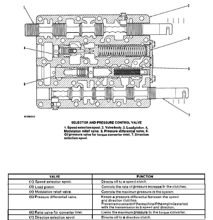
SELECTOR AND PRESSURE CONTROL VALVE
1. Speed selection spool. 2. Valve body. 3. Load pieton. 4.
Modulation relief valve. 5. Pressure differential valve. 6.
Oil pressure valve for torque converter inlet. 7. Direction
selection spool.
The selector and pressure control valve is inside
Direction selection spool (7) is connected through
the top cover of the transmission.
the transmission neutralizer to the direction control
Speed selection spool (1) is connected to the speed
cable from the transmission control lever.
control cable from the transmission control lever.
VALVE
FUNCTION
(1) Speed selection spool.
Directs oil to a speed clutch.
*
(3) Load piston.
Controls the rate of pressure increase in the clutches.
(4) Modulation relief valve,
Controls the maximum pressure in the system.
(5) Pressure differential valve.
Keeps a pressure differential between the speed
and direction clutches.
Prevents movement of the machine if the engine is started
with the transmission in a speed and direction.
(6) Ratio valve for converter inlet.
Limits the maximum pressure to the torque converter.
(7) Direction selection SDOOI.
I
Directs oil to a direction clutch.
I
3-41


