TM 5-3805-258-24-1
P O W E R T R A I N
S Y S T E M S O P E R A T I O N
TRANSMISSION HYDRAULIC CONTROLS
INTRODUCTION
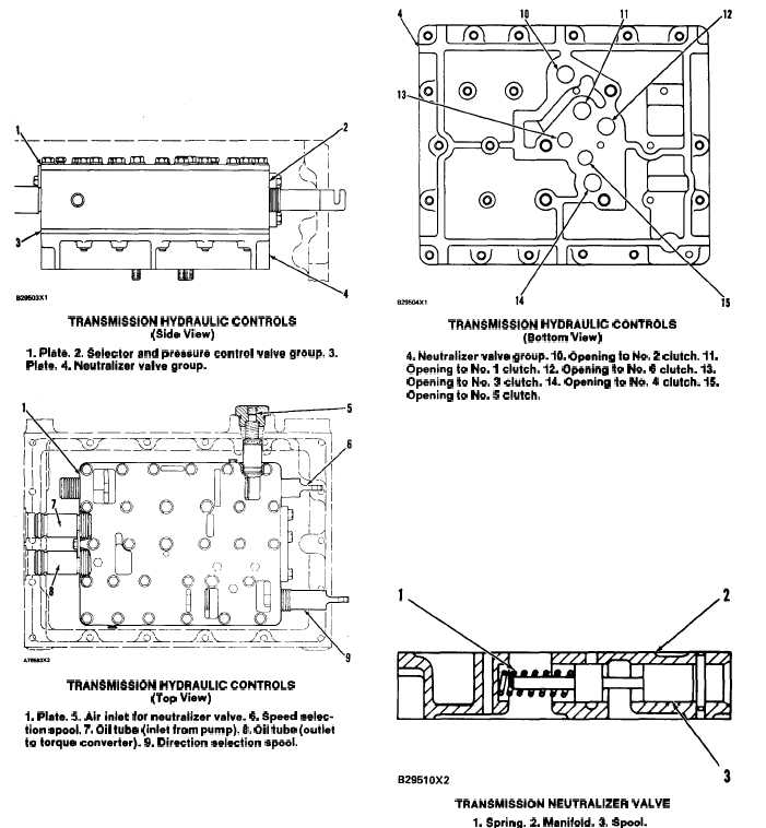
The transmission hydraulic controls are installed
on the transmission planetary. The controls have a
top plate (1), selector and pressure control valve
group (2), plate (3) and neutralizer valve group (4).
TRANSMISSION HYDRAULIC CONTROLS
(Side View)
1. Plate. 2. Selector and pressure control velve group. 3.
Plate. 4. Neutralizer valve group.
TRANSMISSION HYDRAULIC CONTROLS
(Top View)
1. Plate. 5. Air inlet for neutralizer valve. 6. Speed selec-
tion spool. 7. Oil tube (inlet from pump). & Oil tube (outlet
to torque converter). 9. Direction selection spool.
Inlet oil for operation of the hydraulic controls
comes from the filter and goes through tube (7) to the
pressure control valve.
Oil, for operation of the torque converter, goes
through tube (8) and an oil line to the torque
converter.
Air pressure for operation of the neutralizer valve,
comes through air inlet (5). This air pressure is from
the brake system.
3-40
TRANSMISSION HYDRAULIC CONTROLS
(Bottom View)
4. Neutralizer valve group. 10. Opening to No. 2 clutch. 11.
Opening to No. 1 clutch. 12. Opening to No. 6 clutch. 13.
Opening to No. 3 clutch. 14. Opening to No. 4 clutch. 15.
Opening to No. 5 clutch.
Oil, to the clutches, is sent through openings (10),
(1l), (12), (13), (14) and (15) in the bottom mani-
fold to the appropriate clutches for the speed and
direction selected.
NEUTRALIZER VALVE
TRANSMISSION NEUTRALIZER VALVE
1. Spring. 2. Manifold. 3. Spool.
The neutralizer valve is in the bottom manifold of
the hydraulic controls.
The neutralizer valve is activated by the left brake
pedal. When the left brake pedal is pushed, brake
system air pressure moves spool (3) against the force