P O W E R T R A IN
TM 5-3805-258-24-1
S Y S T E M S O P E R A T I O N
OUTPUT TRANSFER GEARS
OUTPUT TRANSFER GEARS
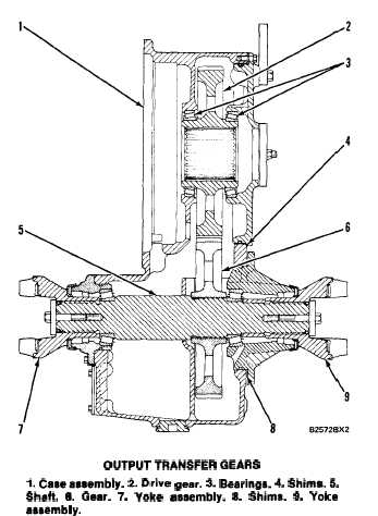
l. Caseassembly. 2. Drive gear. 3. Bearinga. 4. Shims. 5.
Shaft. 6. Gear. 7. Yoke aaaembly. 8. Shims. 9. Yoke
aaaembly.
Drive gear (2) is engaged with gear (6). Driven
gear (6) is connected to shaft (5) by splines. Yoke
assemblies (7) and (8) are connected to shaft (5) by
splines. Yoke assembly (7) is connected to the short
drive shaft that goes to the rear differential. Yoke
assembly (9) is connected to the drive shaft that goes
to the bearing cage and then to the front differential.
The flow of power through the output transfer
gears is:
. . . From transmission output shaft to drive gear (2).
. . . From gear (2) to driven gear (6).
. . . From driven gear (6) to shaft (5).
At shaft (5) the flow of power divides as follows:
. . . Part of the power goes from yoke assembly (7)
through a drive shaft to the rear differential.
. . . Part of the power goes from yoke assembly (9)
through a drive shaft and bearing cage to the
front differential.
Shims (4) are used to make an adjustment to the
end play of gear (2).
Shims (8) are used to make an adjustment to the
end play of shaft (5).
The output transfer gears are at the output side of
the transmission. The transmission output shaft is
connected to drive gear (2) by splines.
OUTPUT TRANSFER GEAR LUBRICATION
Since the transfer gear case is also the reservoir for
the transmission circuit, all return oil goes to the
bottom of the case. The movement of the gears in the
oil causes oil to be thrown on all the components.
3-51