TM 5-3805-258-24-1
P O W E R T R A IN
N O S P I N D I F F E R E N T I A L G R O U P
S Y S T E M S O P E R A T I O N
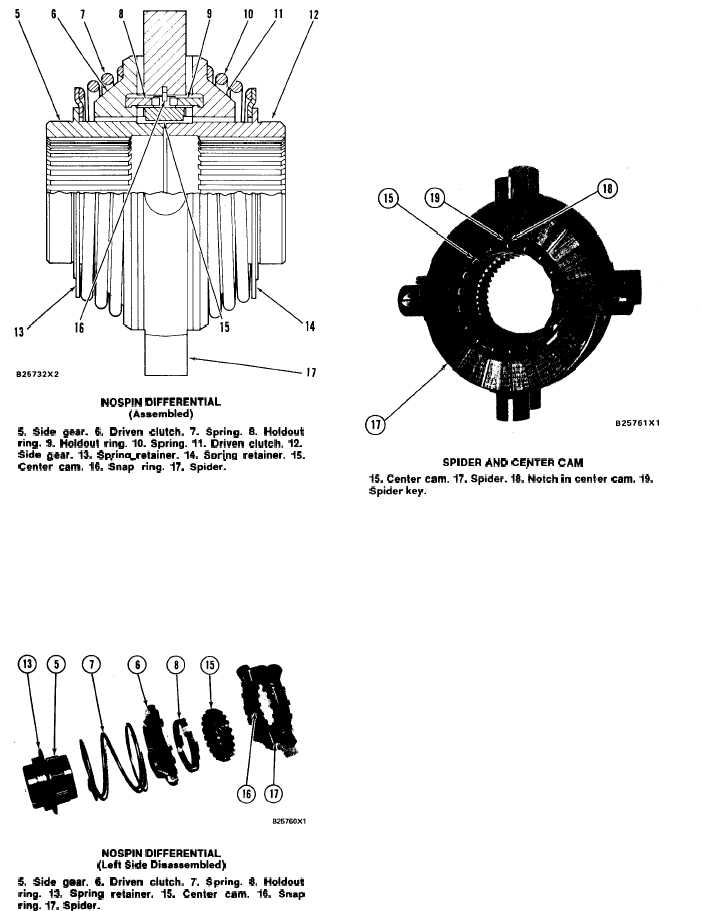
NOSPIN DIFFERENTIAL
(Assembled)
5. Side gear. 6. Driven clutch. 7. Spring. 8. Holdout
ring. 9. Holdout ring. 10. Spring. 11. Driven clutch. 12.
Side aear. 13. Swing retainer. 14. Spring retainer. 15.
Cente; cam. 16. Sna~ ring. 17. Spide~
-
Spider (17) is fastened to the differential case and
turns at the speed of the bevel gear. The spider has
clutch teeth on both sides. The spider also has one
long tooth. The long tooth is spider key (19). Center
cam (15) fits inside the spider and is held in position
by snap ring (16). The center cam is turned by spider
key (19) which fits inside notch (18). The spider key
pushes on either side of notch (18). The direction of the
NOSPIN DIFFERENTIAL
(Left Side Disassembled)
5. Side gear. 6. Driven clutch. 7. Spring. 8. Holdout
ring. 13. Spring retainer. 15. Center cam. 16. Snap
ring. 17. Spider.
machine, forward or reverse, controls which way the
spider turns and which side of notch (18) gets the force.
Springs (7) and (10) fit between the side gears and
spring retainers (13) and (14). The outside splines of
the spring retainers are connected to the inside
splines of the driven clutches. The force of the springs
holds the driven clutches against spider (17) and the
side gears against the differential case.
SPIDER AND CENTER CAM
15. Center cam. 17. Spider. 18. Notch in center cam. 19.
Spider key.
Driven clutches (6) and (11) are the same. Each
driven clutch has a cam (21) which is part of the
clutch. The teeth on the cam engage with the teeth of
center cam (15). The teeth of the drive clutches
engage with the teeth of spider (17). An annular (in
the shape of a circle) groove is between the teeth of
the driven clutches and the teeth of the cams.
Holdout rings (8) and (9) are the same. Each
holdout ring fits in the annular groove between the
teeth of the driven clutches and the teeth of the cams.
The teeth of the holdout rings engage with the
notches in the center cam. Notch (20) in the holdout
ring engages with spider key (19). The spider key
controls the movement of the holdout ring in relation
to the spider. There is no connection, except friction,
between the holdout rings and the driven clutches.
3-55


