TM 5-3805-258-24-1
P O W E R T R A IN
S Y S T E M S O P E R A T I O N
DIFFERENTIALS
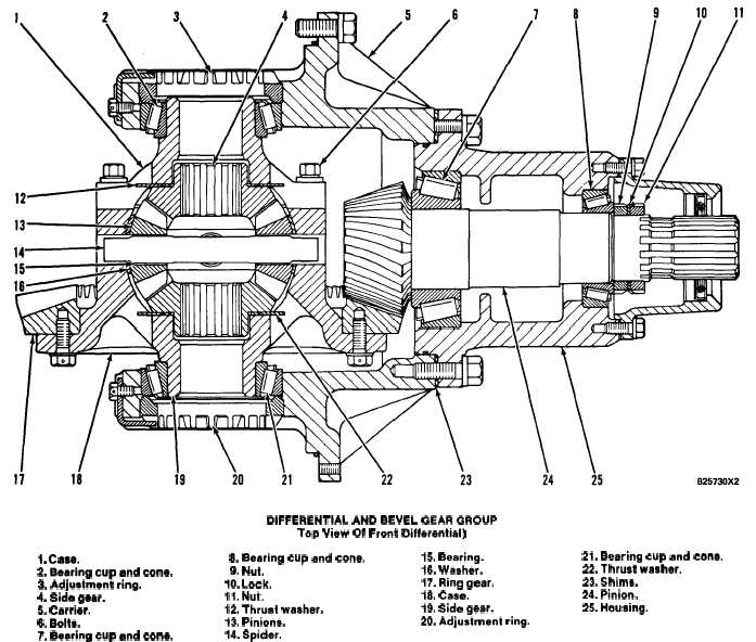
DIFFERENTIAL AND BEVEL GEAR GROUP
Top View Of Front Differential)
1. Case.
8. Bearing cup and cons.
2. Bearing cup and cone.
9. Nut.
3. Adjustment ring.
10. Lock.
4. Side gear.
11. Nut.
5. Carrier.
12. Thrust waahar.
6. Bolts.
13. Piniona.
7. Bearing cup and cone.
14. Spider.
A differential divides or causes a balance of the
power which is sent to the wheels. When one wheel
turns slower than the other, as in a turn, the differen-
tial lets the inside wheel go slower in relation to the
outside wheel. The differential still sends the same
amount of torque to each wheel.
Bevel pinion (24) is connected to a yoke. The yoke
assembly is connected to a universal joint from the
output transfer gears. Pinion (24) is connected to the
yoke assembly by splines. Pinion (24) is engaged with
ring gear (17). Ring gear (17) is fastened to the
differential group. Differential carrier (5) is fastened
to the axle housing.
15. Bearing.
21. Bearing cup and cons.
16. Waaher.
22. Thrust waaher.
17. Ring gear.
23. Shims.
18. Case.
24. Pinion.
19. Side gear.
25. Housing.
20. Adjustment ring.
The differential group has a case (18). Ring gear
(17) is fastened to case (18). Case (18) is fastened to
case (1) by bolts (6). Inside the differential group is
side gear (4), spider (14), four pinions (13) and side
gear (19). Spider (14) is installed between the two
cases. When the cases are turned, the spider turns.
Pinions (13) are installed on the spider and are en-
gaged with the teeth of side gears (4 and 19). The
axle shafts are connected to the side gears by splines.
Side gears (4 and 19) turn against thrust washers (12
and 22). Pinions (13) turn on bearings (15).
Nuts (9 and 11) and lock (10) are used to make an
adjustment to the end play (bearing preload) of bear-
ings (7 and 8) for pinion (24).
3-52