TM 5-3805-258-24-1
POWER TRAIN
NOSPIN DIFFERENTIAL GROUP
S Y S T E M S O P E R A T I O N
CLUTCH AND HOLDOUT RING
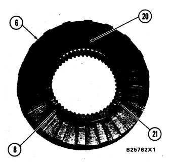
6. Driven clutch. 8. Holdout ring. 20. Notch in holdout
ring. 21. Cam.
OPERATION OF NOSPIN DIFFERENTIAL
When a wheel is made to turn faster than the speed
of the bevel gear, the “clutch action” (the stopping of
power to drive axle) of the NoSpin differential will
let this axle turn faster than the speed of the bevel
gear.
The “clutch action” of the NoSpin differential is
as follows: If spider (17) turns, spider key (19) lo-
cates center cam (15) and the spider and the center
cam turn at the speed of the bevel gear. The center
cam turns holdout ring (8) and cam (21) at the speed
of the bevel gear. The spider turns driven clutch (6)
at the speed of the bevel gear. The driven clutch turns
the side gear, axle and wheel at the speed of the bevel
gear.
When the wheel is made to turn faster than the
speed of the bevel gear, the teeth of center cam (15)
work like ramps and the teeth of cam (21) move up
the teeth of the center cam. This action causes driven
clutch (6) to become disengaged (not engaged) with
the spider. The driven clutch pulls holdout ring (8)
out of the grooves in the center cam. The friction
between the holdout ring and driven clutch turns the
holdout ring until notch (20) in the holdout ring
engages with spider key (19). The holdout ring is now
turned by the spider key at the speed of the bevel
gear. The teeth of the holdout ring are now in a
position so they can not engage the notches in the
center cam. The driven clutch and cam move around
the holdout ring at a speed faster than the speed of
the bevel gear. The holdout ring keeps the driven
clutch and cam from being engaged (engagement)
with the center cam and spider. The driven clutch,
cam, axle shaft and wheel now turn freely.
The opposite side clutch, cam and holdout ring are
held engaged to the center cam and spider by spring
(7) as long as the driven wheel turns slower.
When the speed of the wheel that is not engaged
becomes slower and near the speed of the bevel gear,
the resistance of the ground to the wheel causes the
torque on this wheel to be in a small reverse direction.
This causes the driven clutch and cam to turn in a
direction opposite the direction of the bevel gear. The
friction between the holdout ring and the driven
clutch causes the holdout ring to move in a direction
opposite the direction of the bevel gear. Notch (20) in
the holdout ring moves away from spider key (19).
When the teeth of the holdout ring are in a position to
engage the notches in center cam (15), the force of
the spring causes the driven clutch and cam to move
to the inside. The driven clutch pushes the holdout
ring. The holdout ring now engages the center cam
and is turned at the speed of the bevel gear. The teeth
of cam (21) now engage the center cam and the teeth
of the drive clutch engage the spider. At this time,
both wheels are turned at the same speed.
NOTE: When both wheels are turned at the same
speed they do not necessarily have equal torque. For
example: When one wheel starts to turn faster on ice
(tends to spin), both clutches engage and both wheels
turn at the same speed. The wheel that is on ice will
have less torque.
3-56


