TM 5-3805-258-24-1
S Y S T E M S O P E R A T I O N
S T E E R I N G S Y S T EM
AMPLIFIED STEERING SYSTEM
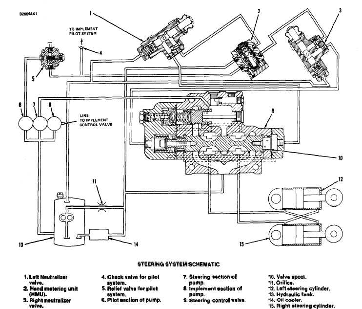
STEERING SYSTEM SCHEMATIC
I. Left Neutralizer
4. Check valve for pilot
valve.
syetem.
2. Hand metaring unit
5. Relief valve for pilot
(HMU).
system.
3. Right neutralizer
6. Pilot section of pump.
valve.
The system can be divided into two parts; the pilot
system and the steering system. The oil for both
systems comes from a hydraulic pump that has three
sections. Pilot section (6) provides oil for both the
steering and implement pilot systems. The pilot sec-
tion also has relief valve (5) in it which controls the
maximum pressure in the pilot systems. Steering
section (7) provides oil for the steering system. Im-
plement section (8) provides oil for the implement
system.
The pilot system controls the movement of spool
(10) in steering control valve (9). The components of
the pilot system are pilot section (6) and relief valve
(5) of the hydraulic pump, hand metering unit.
3-60
7. Steering section of
10. Valve spool.
pump.
11. Orifice.
6. Implement section of
12. Left steering cylindar.
pump.
13. Hydraulic tank.
9. 5teating control valve.
14. Oil cooler.
15. Right steering cytinder.
(HMU) (2), and left and right neutralizer valves (3)
and (1).
Pump oil from pilot section (6) is always available
at constant pressure to the hand metering unit. The
hand metering unit is a small hydraulic pump that is
used as a metering and directional valve. It sends
pilot oil through one of the neutralizer valves when
the steering wheel is turned. The neutralizer valve
stops the flow of pilot oil when the machine is turned
completely to the right or left. If the machine is not
turned completely, the pilot oil will flow through the
neutralizer valve to the respective end of spool (10).
The oil then flows across the metering orifices in the
spool. The flow across the orifices causes the spool to
move.