TM 5-3805-258-24-1
S T E E R I N G S Y S T EM
A M P L I F I E D S T E E R I N G S Y S T EM
S Y S T E M S O P E R A T I O N
If an outside force keeps the machine from turn-
ing, the pressure in outlet (6) will increase. This
pressure increase is also felt against the pilot valve
and flow control valve. The pressure against flow
control valve (18) causes it to move to the left. This
lets more oil flow to the cylinders. If the pressure goes
above the relief valve setting, the pilot valve will
open.
Return oil from the cylinders enters outlet (4). It
flows into return passage (13) and then through out-
let (5).
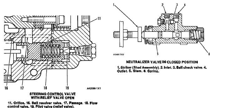
STEERING CONTROL VALVE
WITH RELIEF VALVE OPEN
11. Orifice. 16. Bell resolver velve. 17. Passege. 18. Flow
control valve. 19. Pilot valve (relief valve).
When the pilot valve opens, oil flows through pas-
sage (17) and past the pilot valve. The flow of oil past
orifice (11) causes a lower pressure in the chamber
for the flow control spring. This lets the pressure of
the oil in inlet passage (15) move flow control valve
(18). Oil from inlet (15) can flow through the holes in
the flow control valve, which now works as a dump
valve. This releases the extra pressure from the cir-
cuit. When the outside force is gone and the pressure
is reduced, the flow control valve and pilot valve
return to their normal positions.
Left Turn Position
The control valve operation for a left turn is similar
to that for a right turn. Pilot oil enters inlet passage
(10) and moves the spool to the right. Pump oil from
inlet (15) flows through the slots in spool (12) to
outlet (4). This oil flows to the head end of the right
steering cylinder and to the rod end of the left steer-
ing cylinder. The pressure of this oil moves the cy-
linder rods and the machine turns to the left.
When the valve spool is in the left turn position, the
pressure of the oil to the cylinders is felt through
passage (14) and across the ball resolver valve. This
same pressure is felt through passage (17) and at
pilot valve (19). The remainder of the relief valve
operation is the same for the LEFT TURN position
and the RIGHT TURN position.
NEUTRALIZER VALVE
NEUTRALIZER VALVE IN CLOSED POSITION
1. Striker (Stud Assembly). 2. Inlet. 3. Ball check valve. 4.
Outlet. 5. Stem. 6. Srxina.
The neutralizer valve stops the flow of pilot oil to
the steering control valve at the end of a complete
turn. This stops the steering action before the ma-
chine turns against the frame stops.
The pilot oil that flows from the hand metering
unit (HMU) to the steering control valve must first
pass through the right or left neutralizer valve. The
oil from the HMU goes into the valve through inlet
(2). The oil flows around stem (5) and through outlet
(4) to the steering control valve.
When the machine is at the end of a complete right
turn, striker (1) comes in contact with stem (5) of the
right neutralizer valve. It moves the stem until pilot
oil can not flow from inlet (2) to outlet (4). This stops
the flow of oil across the metering orifices in the main
control spool. The steering valve spool will then re-
turn to NEUTRAL, and the steering action of the
machine stops.
Before steering action can start back to the left, oil
must flow from the return end of the steering valve
spool through the right neutralizer valve. Since stem
(5) has the oil stopped, the return oil from the end of
the spool must flow past ball check valve (3). This
lets the steering valve spool move and the steering
action starts,
As the machine moves to the left a small amount,
striker (1) will move away from the stem. This lets
the pilot oil flow around the stem again, and the ball
check valve closes.
3-66