TM 5-3805-258-24-1
S T E E R I N G S Y S T E M
S U P P L E M E N T A L S T E E R I N G S Y S T E M
The main components for the supplemental steer-
ing system are: supplemental steering pump (18),
diverter valve (17) and flow switch (16).
The supplemental steering pump is a ground dri-
ven pump; it is turned as long as the machine moves.
The pump gets its power from the output transfer
gears of the transmission.
When the engine is running, primary steering
pump section (7) sends oil through diverter valve
(17) to steering control valve (9). This oil is used to
operate the steering cylinders.
As soon as the machine starts to move, oil is also
sent from supplemental steering pump (18) to the
diverter valve. When the machine moves and the
engine rpm is less than 1450 ± 150 rpm, the oil from
the supplemental steering pump and primary steer-
ing pump section is combined (flows together) in
the diverter valve. This oil flows from the diverter
valve to the steering control valve.
When the machine moves and the engine rpm is
more than 1450 ± 150 rpm, the diverter valve sends
the oil from the supplemental pump back to the
hydraulic tank. The oil supply for the steering con-
trol valve will then come only from the primary
steering pump section. If, under this condition,
there is a primary steering pump failure, the diver-
ter valve will immediately send the oil from the
supplemental pump back to the steering control
valve.
Flow switch ( 16) is installed on the elbow for the
primary steering pump section. It is shown on the
schematic between the primary steering pump sec-
tion and diverter valve. This flow switch warns the
operator of a failure of the primary steering pump
section or lines.
DIVERTER VALVE
The main components of the diverter valve are:
diverter spool (1), check valves (8) and (11), and
reversing spool (14).
When the engine is running, the oil from the pri-
mary steering pump section goes through inlet (10)
and orifice (7) to check valve (8). The force of the oil
opens the check valve. The oil flows past the check
valve, and through outlet (5) to the steering control
valve. Check valve (11) will not let the primary oil
flow into passage (3).
The pressure of the oil before orifice (7) is more
than the pressure of the oil after the orifice. These
pressures are also felt through passage (9) and (6)
respectively.
S Y S T E M S O P E R A T I O N
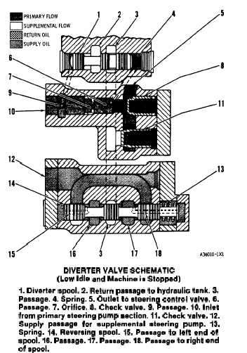
DIVERTER VALVE SCHEMATIC
(Low Idle and Machina ia Stopped)
1. Diverter spool. 2. Return paasage to hydraulic tank. 3.
Passage. 4. Spring. 5. Outlet to steering control valve. 6.
Paasage. 7. Orifice. 6. Check valve. 9. Paasage. 10. Inlet
from primary steering pump section. 11. Check valve. 12.
Supply paasage for supplemental steering pump. 13.
Spring. 14. Reversing spool. 15. Paeaage to left end of
spool. 16. Paasage. 17. Paasage. 18. Paaaage to right and
of spool.
The pressure of the oil is the same before the
orifice and to the left end of diverter spool (1). The
pressure of the oil after the orifice is the same as the
pressure of the oil to the right end of the spool.
As the engine rpm increases, the flow from the
primary steering pump section increases also. Be-
cause of this increased flow past orifice (7), there
is an increase in the difference of the oil pressure
before and after the orifice. When the force of the
oil on the left end of the spool is more than the total
force of the oil and the spring on the right end, the
diverter spool will move to the right. This takes
place when the engine rpm is 1450 ± 150 rpm.
There is no oil sent from the supplemental steering
pump until the machine moves. When the machine
moves, the pump is turned by the output transfer
gears. Oil from the hydraulic tank is supplied to the
supplemental pump through passage (12). Oil flows
from the hydraulic tank through passage (12), to
reversing spool (14).
When the machine moves in a forward direction,
the supplemental pump sends pressure oil into pas-
sage (17). The pressure of this oil is felt through
3-68