S I N G L E
C Y L I N D E R
A l R C O M P R E S S O R
TM 5-3805-258-24-1
S Y S T E M S
O P E R A T I O N
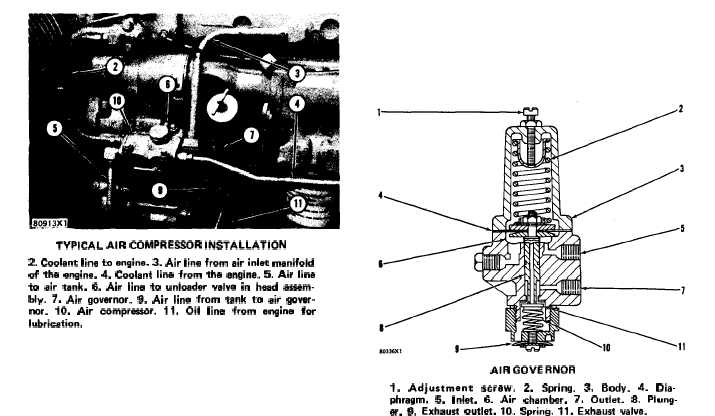
TYPICAL AIR COMPRESSOR INSTALLATION
2. Coolant line to engine. 3. Air line from air inlet manifold
of the engine. 4. Coolant line from the angine. 5. Air line
to air tank. 6. Air Iina to unloader valve in haad aaaam-
bly. 7. Air governor. 9. Air line from tank to air govar-
nor. 10. Air compressor. 11. Oil line from engine for
lubrication.
Components connected to the air line (13) from
the air tank (1) use the air in the tank and the
pressure of the air gets a decrease. When the pres-
sure of the air (getting less and less) gets to the cut
in pressure setting of the air governor, the plunger
in the air governor closes. Now the air from the
line (9) can not go through the line (6) to the
unloader valve in the head assembly. The air goes
out of the line (6) and the unloader valve moves
away from the inlet valve. The inlet valve can again
open and close with the movement of the piston.
Air from the air compressor (10) now goes to the
air tank (1).
AIR GOVERNOR
NOTE: On models 950BSCE and 950BNSCE the
air governor is located on top of the air compressor
instead of the back.
A line from the air tank is connected to inlet (5)
of the air governor. The pressure of the air in inlet
(5) and in chamber (6) is the same as the pressure
of the air in the tank. The air in inlet (5) also goes
into an air passage in plunger (8). Spring (10) holds
exhaust valve (11) against the opening in the end
of the air passage and the air can not get out of
plunger (8).
As the air compressor puts more air into the
tank the pressure of the air in the tank and also in
chamber (6) gets an increase. The pressure of the
air in chamber (6) moves diaphragm (4) against the
force of spring (2). The diaphragm also moves
plunger (8). Spring (10) keeps the exhaust valve
(11) against the plunger as it moves. The cut out
pressure setting of the air governor is when the
pressure of the air in chamber (6) has moved dia-
phragm (4) and plunger (8) until spring (10) moves
exhaust valve (11) against the seat in body (3) and
the air passage in the end of the plunger is open.
Now the air from the tank goes through inlet (5),
through the air passage in plunger (8) and through
outlet (7) to the unloader valve in the cylinder
head of the air compressor.
AIR GOVERNOR
1.
Adjustment
straw.
2.
Spring.
3.
Body.
4.
Dia-
phragm. 5. Inlat. 6. Air chamber. 7. Outlet. 8. Plung-
er. 9. Exhaust outlet. 10. Spring. 11. Exhaust valve.
When the air in the tank is used, the pressure of
the air in the tank gets a decrease. Now spring (2)
moves diaphragm (4) and plunger (8). The cut in
pressure is when the pressure of the air in the tank
and in chamber (6) is less than the force of spring
(2) and the spring moves plunger (8) far enough to
move exhaust valve (11) away from the seat in
body (3). Now the air from the unloader valve goes
into outlet (7) and through exhaust outlet (9) and
the unloader valve lets the inlet valve for the air
compressor operate.
Adjustment screw (1) can be turned to either
make an increase or a decrease in the cut out pres-
sure setting of the air governor. The cut in pressure
is always approximately 15 psi (1.05 kg/cm2) less
than the cut out pressure setting.
AIR COMPRESSOR LUBRICATION
An oil line from the engine lubricating oil sys-
tem is connected to opening (1) in the end cover of
the air compressor.
Pressure oil from opening (1) goes through an
opening in the bearing and the main journal of the
crankshaft gets lubrication. The oil goes through
opening (5) in the main bearing journal, through a
passage in the crankshaft and through opening (4)
in the rod bearing journal. With the oil going out
through opening (4) and running out between the
3-127