B A S I C B L O C K
TM 5-3805-258-24-1
T E S T I N G A N D A D J U S T I NG
BASIC BLOCK
PISTON RING GROOVE GAUGE
Make reference to GUIDELINE FOR REUSA-
BLE PARTS: PISTONS AND CYLINDER
LINERS, Form No. SEBF8001.
The 5P4812 KEYSTONE PISTON RING
GAUGE GROUP is necessary for measuring these
grooves. Put the pin end of gauge “2” in the groove at
four places around the circumference. Do this to both
grooves. The flat edge of the gauge must be between
the grooves. If there is clearance between the flat
edge of the gauge and the piston at all test locations,
for both grooves, the piston is reusable. If the flat
edge is in contact with the piston, at any of the test
locations, the piston is not reusable. Install a new
piston.
5 P 4 8 1 2 K E Y S T O N E P I S T ON
R I N G G R O O V E G A U G E G R O U P
CONNECTING RODS AND PISTONS
Use the 7S9470 Piston Ring Expander to remove
or install piston rings.
Use the 5P3525 Piston Ring Compressor to install
pistons into cylinder block.
Tighten the connecting rod nuts in the step se-
quence that follows:
1. Put engine oil on threads.
2. Tighten both nuts to 40 ± 4 N-m (30 ± 3 lb. ft.).
3. Put a mark on each nut and cap.
4. Tighten each nut 90° from the mark.
The connecting rod bearings must fit tightly in the
bore in the rod. If bearing joints or backs are worn
(fretted), check for bore size as this is an indication of
wear because of looseness.
CONNECTING ROD AND MAIN BEARINGS
Bearings are available with 0.25 mm (.010 in.),
0.51 mm (.020 in.) and 0.76 mm (.030 in.) smaller
inside diameter than the original size bearings. These
bearings are for crankshafts that have been
“ground” (made smaller) than the original size.
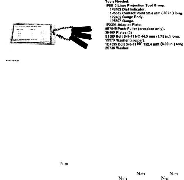
CYLINDER LINER PROJECTION
Tools Needed:
1P5510 Liner Projection Tool Group.
1P2403 Dial Indicator.
1P5512 Contact Point 22.4 mm (.88 in.) long.
1P2402 Gauge Body.
1P5507 Gauge.
1P2394 Adapter Plate.
8B7548 Push-Puller (crossbar only).
3H465 Platea (2)
S1589 Bolt 5/8-11 NC 44.5 mm (1.75 in.) long.
1S379 Washer (copper).
1D4595 Bolt 5/8-11 NC 152.4 mm (6.00 in.) long.
2S736 Washer.
The correct cylinder liner projection is important
to prevent a leak between the liner, cylinder head,
and block. Check cylinder liner projection above the
spacer plate as follows:
1. Be sure that the surfaces of the cylinder block,
cylinder liner, and the spacer plate are clean.
2. Install the spacer plate gasket and spacer plate
(4) on the cylinder block. Use S1589 Bolts (1)
with two 1S379 Washers on each bolt to hold the
spacer plate to the cylinder block. Put two bolts
with washers on each side of the opening for the
cylinder liner. Tighten the bolts evenly, in four
steps; 14 N·m (10 lb. ft.), 35 N·m (25 lb. ft.), 70
N·m (50 lb. ft.), and 95 N·m (70 lb. ft.).
NOTE: To keep from moving bolts and washers as
each liner is checked install two bolts with washers on
each side of each cylinder liner, along the complete
length of the spacer plate.
3. Install the cylinder liner without seals in the
cylinder block. Put adapter plate (7) on the cy-
linder liner as shown. Install crossbar (2) with
1D4595 Bolts (3), 2S736 Washers, and 3H465
Plates (5) as shown. Tighten the bolts evenly, in
four steps; 7 N-m (5 lb. ft.), 20 Nom (15 lb. ft.),
35 N.m (25 lb. ft.) and 70 N.m (50 lb. ft.). The
measurement from the bottom of crossbar (2) to
the spacer plate, must be the same on both sides
of the cylinder liner.
4-35