TM 5-3805-258-24-1
B A S I C B L O C K
T E S T I N G A N D A D J U S T I NG
I
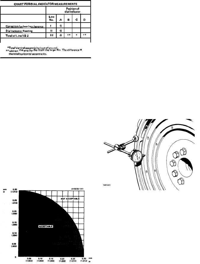
CHART FOR DIAL INDICATOR MEASUREMENTS
Position of
dial indicator
Line
No.
A
B
c
D
Correction for bearing clearance
I
o
Dial Indicator Reading
II
o
Total of Line 1 & 2
Ill
o
“+
“
““
“Total Vertical eccentricity (out of mu nd).
.* “~t,ect the Sma IIer No from the larger No. The difference ls
the t@al horizontal eccentricity.
3.
4.
5.
6.
7.
8.
9.
Turn the crankshaft to put the dial indicator at
(A). Adjust the dial indicator to “0” (zero).
Turn the crankshaft counterclockwise to put the
dial indicator at (B). Write the measurement in
the chart.
Turn the crankshaft counterclockwise to put the
dial indicator at (C). Write the measurement in
the chart.
Turn the crankshaft counterclockwise to put the
dial indicator at (D). Write the measurement in
the chart.
Add lines I & II by columns.
Subtract the smaller number from the larger
number in line III in columns (B) & (D). The
result is the horizontal “eccentricity” (out of
round), Line III, column (C) is the vertical
eccentricity.
On the graph for total eccentricity find the point
of intersection of the lines for vertical eccentri-
city and horizontal eccentricity.
10. If the point of intersection is in the range marked
“Acceptable” the bore is in alignment. If the
point of intersection is in the range marked “Not
Acceptable” the flywheel housing must be
changed.
Face Runout (axial eccentricity)
of the Flywheel
1.
2.
3.
4.
Install the dial indicator as shown. Put a force on
the crankshaft the same way before the indicator
is read to be sure the crankshaft end clearance
(movement) is always removed.
Set the dial indicator to read 0.0 mm (.000 in.).
Turn the flywheel and read the indicator every
90°.
The difference between the lower and higher
measurements taken at all four points must not
be more than 0.15 mm (.006 in.), which is the
maximum permissible face runout (axial eccen-
tricity) of the flywheel.
C H E C K I N G F A C E R U N O U T O F T H E F L Y W H E E L
Bore Runout (radial eccentricity)
of the Flywheel
1. Install the dial indicator (3) and make an adjust-
ment of the universal attachment (4) so it makes
contact as shown.
2. Set the dial indicator to read 0.0 mm (.000 in.).
3. Turn the flywheel and read the indicator every
90°.
4-38