TM 5-3805-258-24-1
E L E C T R I C A L
S Y S T E M
T E S T I N G
A N D
A D J U S T I N G
Pinion Clearance Adjustment
(Delco-Remy)
6.
7.
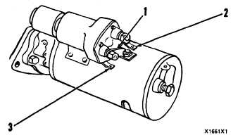
C O N N E C T I O N F O R C H E C K I N G P I N I O N C L E A R A N CE
1. Conneotor from MOTOR terminal on solenoid to mo-
tor, 2. SW terminel. 3. Ground terminal.
Whenever the solenoid is installed, make an ad-
justment of the pinion clearance. The adjustment can
be made with the starter motor removed.
1.
2.
3.
Install the solenoid without connector (1) from
the MOTOR connection (terminal) on solenoid
to the motor.
Connect a battery, of the same voltage as the
solenoid, to the terminal (2), marked SW.
Connect the other side of battery to ground ter-
minal (3).
4.
5.
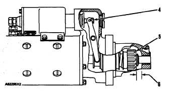
P I N I O N C L E A R A N C E A D J U S T M E N T
4. Shaft nut. 5. Pinion. 6. Pinion clearance.
Connect for a moment, a wire from the solenoid
connection (terminal) marked MOTOR to the
ground connection (terminal). The pinion will
shift to crank position and will stay there until
the battery is disconnected.
Push the pinion toward commutator end to re-
move free movement.
4-42
Pinion clearance (6) must be 8.3 to 9.9 mm (.33
to .39).
Pinion clearance adjustment is made by remov-
ing plug and turning nut (4).


