TM 5-3805-258-24-1
P O W E R
S H I F T
T R A N S M I S S I O N
T E S T I N G A N D A D J U S T I N G
Activate the brakes and use blocks to prevent
machine movement during tests and adjust-
ments to the converter hydraulic system. In-
stall the anti-pivot link. Let only approved per-
sonnel on the machine. Keep other personnel
off the machine and in view of the operator.
Presure
Converter
Inlet Pressure (P3)
Converter
Outlet Pressure
TORQUE CONVERTER PRESSURE CHART
Pressure
I
Governor Control at
(D)
High Idla
965 kPa (140 psi) maximum
with cold oil.
415 k 35 kPa (60 f 5 psi) with axle
shafts installed, selection lever in
FOURTH SPEED, brakes activated
and converter in a stall condition.
Adjustment
NONE
Add or remove
to the amount
of spacers (10).
SEE SPACER CHART.
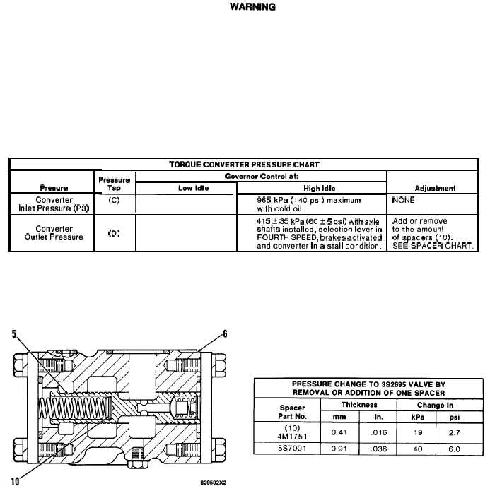
O U T L E T R E L I E F V A L V E F O R T O R Q U E C O N V E R T ER
5. Relief valve for converter outlet. 6. Body of relief valve
for converter outlet. 10. Spacers.
4-46

