P O W E R
S H I F T
T R A N S M I S S I O N
T E S T I N G
A N D
A D J U S T I N G
TM 5-3805-258-24-1
TRANSMISSION CONTROL LINKAGE ADJUSTMENTS
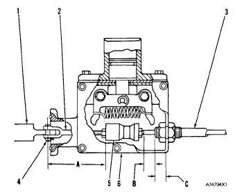
Direction Linkage
1. Put direction selection spool (1) in the NEU-
TRAL position.
2. Make an adjustment to the length of rod (2) so
that distance (A) from the center line of pin (4)
to the face of cam (5) is 80.7 mm (3.18 in.).
3. Install the cable housing in neutralizer housing
(6) so that distance (C) is 12.0 mm (.47 in.).
D I R E C T I O N
C O N T R O L
L I N K A GE
( A t T r a n s m i s s i o n )
1. Direction selection spool. 2. Rod. 3. Cable assembly. 4.
P i n . 5 . C a m . 6 . N e u t r a l i z e r h o u s i n g . A . 8 0 . 7 m m ( 3 . 18
in.). B. 14.0 mm (.55 in.). C. 12.0 mm (.47 in.).
4.
5.
6.
7.
Install cable assembly (3) in cam (5) so that
distance (B) is 14.0 mm (.55 in.)
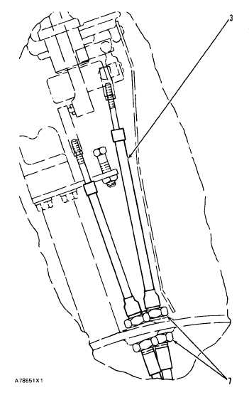
With direction selection spool (1) in the NEU-
TRAL position, loosen nuts (7). Put transmis-
sion selector lever in the NEUTRAL position.
Engage (push in) the neutral lock on the right
side of the steering column (below the steering
wheel).
Tighten nuts (7) to hold cable assembly (3) in
place.
D I R E C T I O N C O N T R O L L I N K A GE
( A t S t e e r i n g C o l u m n )
3. Cable assembly. 7. nuts.
Speed Linkage
1.
2.
3.
4.
5.
Loosen nuts (4) on cable assembly (1).
Remove bolts (6) and washers.
Loosen nut (14) until it is off threads (15) on
cable assembly (1).
Move seal (9) and washer (13) off threads (15).
Turn bracket (5) until it is off threads (15).
4-51