TM 5-3805-258-24-2
ENGINE
DISASSEMBLY AND ASSEMBLY
TURBOCHARGER
11.
1 2.
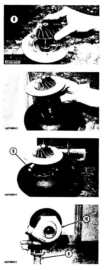
Install compressor wheel (8) on the turbine
shaft.
Put clean engine oil on the threads of the shaft.
Install the nut that holds the compressor wheel
in place. Tighten the nut with tool (D) to a
torque of 2.3 N·m (20 lb.in.). Put a mark on the
nut and shaft. Tighten the nut 100° more.
CAUTION
When the nut is tightened, do not put a
side force on the shaft.
13.
14.
15.
16.
17.
18.
If the turbine housing was removed from
tool (B), put the turbine housing in position
on tool (B).
Put the housing and wheels in position in
the turbine housing respective to the marks
put on the housings at disassembly.
Put 5P3931 Anti-Seize Compound on the
threads of bolts (9). Install the clamps, lock-
plates and the bolts (9). Tighten the bolts to a
torque of 13 ± 1.7 N·m (115 ± 15 lb.in.). Bend
the lockplates against the bolt heads.
Put compressor housing (10) in position on
the backplate assembly respective to the
marks put on the housing and backplate
assembly at disassembly.
Install the clamps, lockplates and bolts that
hold the compressor housing in place. Tighten
the bolts to a torque of 13 ± 1.7 N·m (115 ±
15 lb.in.). Bend the lockplates against the bolt
heads.
Remove the turbocharger from tool (B).
5-54