TM 5-3805-258-24-2
ENGINE
DISASSEMBLY AND ASSEMBLY
FUEL RATIO CONTROL
6. Use tooling (A) to remove snap ring (19).
7. For models 950BNSCE and 950BSCE only,
remove two washers (22) behind snap ring.
8. Remove piston (20) from valve (18).
9. Remove seal (21) from piston (20).
10. Inspect all parts and make replacements if
necessarv.
ASSEMBLE THE FUEL
1278-16
RATIO CONTROL
Tools Needed
A
1P1859
Snap Ring Pliers
1
1.
2.
3.
4.
5.
Put seal (1) on piston (2). Install the seal so the
lip is toward the direction of the center of piston
(2).
Put piston (2) on valve assembly (3). For
models 950BNSCE and 950BSCE only, put
two washers (22) on valve assembly.
Use tooling (A) to put the snap ring (4) in
position.
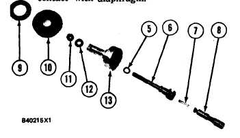
Put O-ring seal (5) in position on valve exten-
sion (6).
Put diaphragm (10) on retainer (13). The outer
lip of the diaphragm must be toward the hole
with thread.
NOTE: Spacer (12) is not used on models
950BNSCE and 950BSCE.
6. Put engine oil on the seal (5) on valve extension
(6) and put valve extension (6) into retainer
(13). Install spacer (12) and nut (11).
7. Put spring (7) into valve extension (6) and
engage internal valve (8) with hook on the valve
extension (6).
8. Put washer (9) on diaphragm (10). The flat
side of washer (9) must be in contact with
diaphragm (10). For models 950BNSCE and
950BSCE, put larger diameter of washer in
contact with diaphragm.
5-82