TM 5-3305-258-24-2
ENGINE
ALTERN
DISASSEMBLY AND ASSEMBLY
ATOR
18.
19.
20.
21.
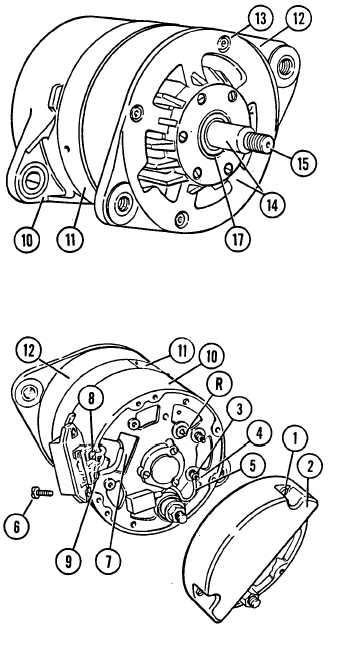
Connect drive end shield (12) and rotor (15)
as an assembly (14) to the rear housing (10)
and stator frame assembly (11). Use marks
made during disassembly to help alignment.
Install four hex-socket head capscrews (13).
DO NOT TIGHTEN.
Insert three 0.3 mm (0.01 in.) feeler gauges
between rotor and stator. Tighten screws
(13) to a torque of 3 to 4 ft. lbs. Remove
feeler gauges.
Connect the field coil lead (with large
diameter hole) to the regulator (7) with a
large diameter screw (9). Connect the recti-
fier lead and the remaining field coil winding
lead to the regulator terminal (7). with a
small diameter screw (8).
NOTE: To maintain the proper field coil lead
22.
23,
24.
polarity, one field coil lead has a small
diameter hole.
Place regulator (7) on rear frame assembly
and install two screws (6).
Install suppression capacitor lead (5) on the
D+ terminal (4) and install nut (3) using a
3/8” wrench.
Install regulator cover (2) and install two
screws (1).
5-12f