ENGINE
TM 5-3805-258-24-2
DISASSEMBLY AND ASSEMBLY
ALTERNATOR
8.
9.
10.
11.
12.
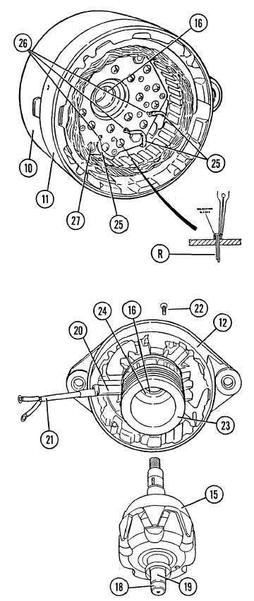
Install two screws (27).
Install “R” terminal, if removed, by solder-
ing the soldering sleeve to the terminal.
Position stator frame (11) on rear frame
(10). Align the marks made during disas-
sembly.
Solder three phase stator winding leads (25)
to rectifier terminals (26).
If removed, install bearing (16) in drive end
frame (12).
NOTE: This is a loose fit bearing.
13. Install intermediate ring (24) in drive end
frame (12).
14. Install field coil winding (23). Winding leads
(21) must fit in deep groove (20). Install six
screws (22). Apply epoxy putty over lead
and groove.
15. Install spacer ring (25).
CAUTION
In the next step, the spacer ring must be supported
so that the bearing inner race is supported.
16.
17.
Install rotor assembly (15) in drive end frame
(12) using a press.
Heat bearing race (18) to 275°F. Install
bearing race on rotor shaft (19).
5-12e