TM 5-3605-258-24-2
ENGINE
DISASSEMBLY AND ASSEMBLY
AIR COMPRESSOR HEAD ASSEMBLY
Models 950BNS and 950BS
REMOVE HEAD ASSEMBLY
11–1065
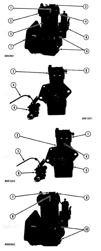
1.
2.
3.
4.
Loosen two set screws (1) and cover (2).
Put alignment marks on head assembly (3)
and on cylinder (5) and also on the cylinder
and on crankcase (7) so parts can be put in
correct location when they are assembled.
Disconnect air line (4) and remove two
bolts (8) and governor assembly (6).
Remove four nuts (9) and remove head
assembly (3).
NOTE: If needed, hit head assembly (3) with a soft
hammer and then remove the head assembly.
INSTALL HEAD ASSEMBLY
12-1065
1. Install new gasket (4) on cylinder (2).
2. Install head assembly (1) on cylinder (2).
3. Put alignment marks on the cylinder and
head assembly together and tighten four nuts
(8). Torque for nuts is 14±3 lb. ft (1.9 ± 0.4
mkg).
4. Install governor assembly (6) on end cover
(5) and tighten bolts (10). Torque for bolts
is 10 lb. ft. (1.38 mkg). Connect air line (3)
to head assembly (1).
5. Tighten cover (7). Torque for cover is 60
lb. ft. (8.3 mkg).
6. Tighten two set screws (9), Torque for set
screws is 50 to 96 lb.in. (57.6 to 110.7
cm kg).
5-14