TM 5-3805-258-242
VEHICLE SYSTEMS
DISASSEMBLY AND ASSEMBLY
STEERING CONTROL VALVE MANIFOLD
Models 950BNSCE and 950BSCE
REMOVE AND INSTALL
STEERING CONTROL VALVE
MANIFOLD 4307-010
Start By:
a. connection of steering frame link lock
1. Drain the oil approximately half way down in
the hydraulic tank.
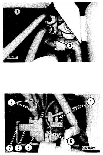
2. Remove the bolts that hold tube (1), and
remove the tube from the rear, of the steering
control valve manifold.
3. Remove the bolts that hold hose (2), and
remove the hose from the rear of the steering
control valve manifold.
4. Disconnect line (7) and hose (4).
5. Remove two hoses (3) and make-up valve (8).
6. Remove bolts (5), and remove steering control
valve manifold (6).
7. Clean and inspect the O-ring seals and make a
replacement if any seals are worn or damaged.
8. Make sure the O-ring seals are in position on
the steering control valve manifold.
9. Put steering control valve manifold (6) in
position, and install bolts (5) that hold it.
10. Install make-up valve (8) and two hoses (3).
11. Connect line (7) and hose (4).
12. Position hose (2), and install the bolts that
hold it. Position tube (l), and install the bolts that
hold it.
13. Fill the hydraulic tank with oil to the correct
level. See the Maintenance Guide.
End By:
a. separation of the steering frame lock link
5-386