TM 5-3805-258-24-2
DISASSEMBLY AND ASSEMBLY
ENGINE
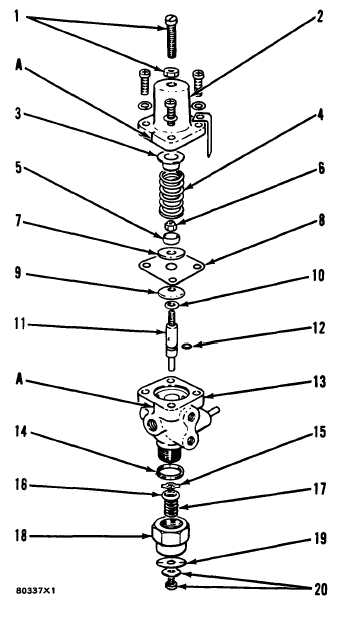
AIR GOVERNOR
Models 950BNS and 950BS
ASSEMBLE AIR GOVERNOR
16-1065
1. Install seal (12) on plunger (11).
2. Put new soft washer (10), follower (9), new
diaphragm (8), follower (7), spring guide (5)
and new nut (6) on plunger (11).
NOTE: The diaphragm is between the chamfered
sides of followers (7) and (9).
3.
4.
5.
6.
A rod with a diameter of .12 in. (3.05 mm)
put in the hole in plunger (11) is used to
hold the plunger when nut (6) is tightened.
Lubricant is put on plunger (11) and in
body (13). Install plunger in body.
Install spring seat (3) in spring (4) and put
them on spring guide (5).
Install cover (2) over spring seat (3) and
spring (4). Mark (A) on cover (2) must be in
alignment with mark (A) on body (11)
when the four lockwashers and screws in
the cover are tightened.
NOTE: The governor identification tag is under
one of the four screws.
7.
8.
9.
10.
Install screw and nut (1) in cover (2). Make
an adjustment for the length of the screw to
get the same measurement before the screw
was removed from the cover.
Install screw and diaphragm washer (20) and
new exhaust diaphragm (19) on exhaust nut
(18).
Install spring (17), spring retainer (16) and
new exhaust valve (15) in exhaust nut (18).
Install washer (14) and exhaust nut (18),
spring retainer and spring in body (13). In-
stall air governor and air line on air compres-
sor.
5-20