OPERATOR’S STATION
TM 5-3805-258-24-2
DISASSEMBLY AND ASSEMBLY
21.
22.
23.
24.
25.
HYDRAULIC CONTROL
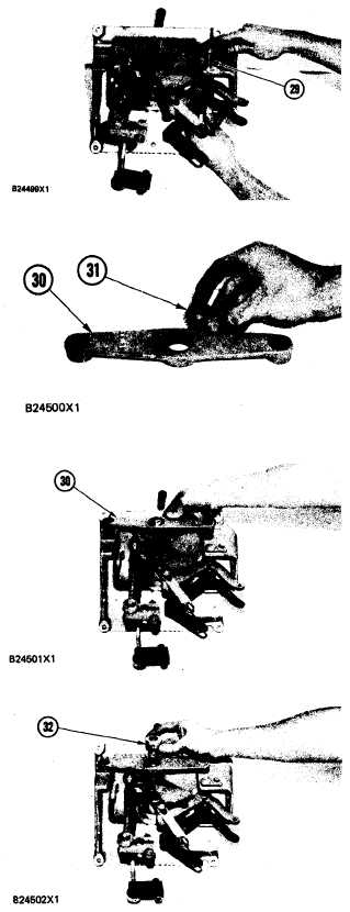
Install shaft assembly (29) to hold the bell-
crank and lever in the panel. Install the bolt and
washer to hold shaft assembly (29) in position.
Install bearing (31) in bracket (30).
Install bracket (30) over the shaft of the lever
assembly. Install the two washers and bolts to
hold bracket (30) to the panel.
For models 950BNS and 950BS, install collar
(32) on the shaft of the lever assembly and
tighten the setscrew. Models 950BNSCE and
950BSCE do not use the collar and set screw.
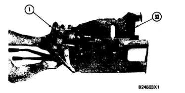
Put panel (1) in position in console (33) and
install the four bo1ts and two nuts to hold the
unit together.
GROUP
5-529


