OPERATOR’S STATION
HYDRAULIC CONTROL
ASSEMBLE HYDRAULIC CONTROL
GROUP
5063-16
Tools Needed
A
B
1P510
Driver Group
1
1P1859
Pliers
1
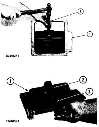
1. Use tool group (A) to install the bearing in
panel (1).
TM 5-3805-258-24-2
DISASSEMBLY AND ASSEMBLY
GROUP
2. Install the knob, stud and locknut on pin (3).
3. Install pin (3) in the top of panel (1) as
shown ‘and tighten screw (2) to hold it.
4. Install detent ball (6), spring (5) and screw
(4) in panel (1).
NOTE: For the third attachment control lever
in the hydraulic control group: (See
illustration accompanying steps 26a-d
4a.
4b.
4c.
4d.
in the disassembly procedure of the
hydraulic control group)
Replace the knob and nut on the end of the
lever assembly.
Install the lever assembly in the panel.
Install the key and lever on the shaft. of the
lever assembly. Tighten clamp bolt.
Fasten the bolts, nuts, washer and link to
the lever.
5-526a