TM 5-3805-262-20
INSTALLATION (SHEET 3 OF 4)
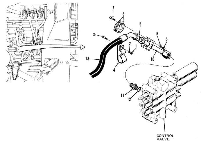
NOTE
Install new tie straps as necessary in following steps.
( 1 0 ) I f n e c e s s a r y , i n s t a l l n e w 0 - r i n g ( 1 2 ) o n c o n n e c t o r ( 1 1 ) ; i n s t a l l c o n n e c t-
or (11) with new 0-ring in control valve inlet port. Tighten securely.
(11) Position tube (10) between connector (11) and hose (13). Connect to con-
n e c t o r ( 1 1 ) a n d f i n g e r t i g h t e n t u b e f i t t i n g .
( 1 2 ) I n s t a l l n e w 0 - r i n g ( 9 ) i n h o s e ( 1 3 ) f i t t i n g.
(13) Connect hose (13) to flange connector on tube (10); loosely install two
f l a n g e s ( 8 ), four capscrews (7), lock washers (6), and nuts (5).
(14) Install clamp (4) on hose (13) and position clamp on tube; install and
tighten capscrew (3), lock washer (2), and nut (1) to secure clamp.
(15) If necessary, adjust positioning of tube (10) and hose (13) to ensure a
t i g h t c o n n e c t i o n.
(16) Tighten tube (10) fitting at connection to connector (11).
(17) Tighten four nuts (5) to 34 to 45 lb-ft.
11-23