TM 5-3805-262-20
INSTALLATION
(1)
( 2)
(3)
( 4)
( 5)
(6)
(7)
(8)
(9)
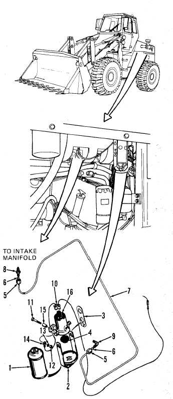
Position solenoid (16) and
install two spacers (15) and
capscrews (11). Connect ter-
minal (14) to one capscrew,
then install two lock washers
(13), and nuts (12).
Connect connector (10) to
solenoid (16) by alining
solenoid contacts with
connector slots and pushing
down firmly on connector.
I n s t a l l f i t t i n g ( 9 ) i n s o l e n o i d
(16) and nozzle (8) in engine
intake manifold.
If tube (7) was replaced,
install two compression nuts
(5) and compression sleeves
(6), one each on each end of
tube (7). Route and connect
t u b e ( 7 ) t o f i t t i n g ( 9 ) a n d
nozzle (8), Position com-
p r e s s i o n s l e e v e i n f i t t i n g a nd
n o z z l e , t h e n t i g h t en
compression nuts securely.
Install new gasket (4) on
solenoid (16).
Install two extension links (3)
o n b a i l ( 2 ) a n d i n s t a l l a s-
sembled parts on solenoid (16)
ears by pulling apart extension
links just enough for them to
clear solenoid ears and alining
holes in extension links with
ears until they are engaged,
then pushing bail (2) gently
downward.
Remove cap and plastic spray
nozzle from new cylinder of
s t a r t i n g f l u i d.
Install new cylinder (1) and
t i g h t e n b a i l ( 2 ) l o c k n u t u n t il
cylinder cannot move.
Reinstall engine left side panels (page 9-17).
4-53