TM 5-3805-262-20
INSTALLATION
(1)
( 2 )
(3)
( 4 )
(5)
(6)
(7)
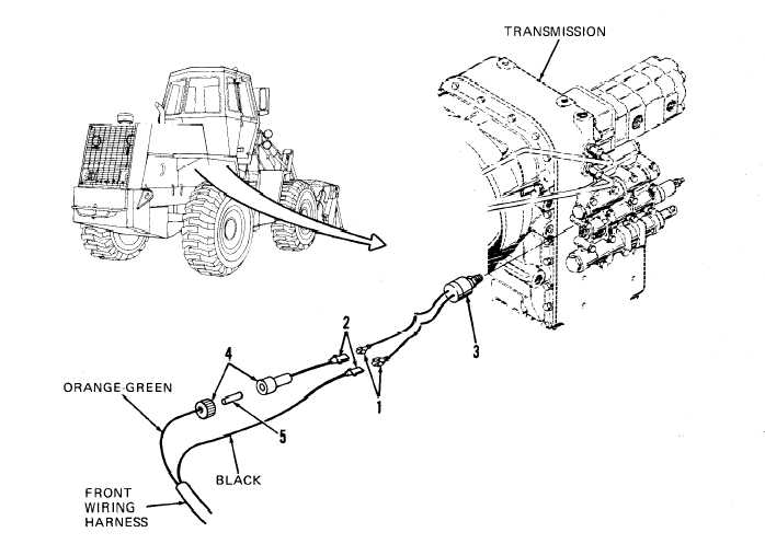
A t r i g h t s i d e o f t r a n s m i s s i o n , a t c o n t r o l v a l v e , i n s t a l l a n d t i g h t en
clutch pressure switch (3).
Install resistor (5) by pushing into long half of fuseholder (4).
Assemble fuseholder (4) halves by grasping both in your fingers, alining,
then firmly pushing them together and twisting clockwise.
Connect wiring harness spade terminals (2) to switch spade terminals (1)
by grasping both in your fingers, alining, then firmly pushing them to-
g e t h e r .
Spray terminals (1 and 2) with electrical cleaner and allow to air dry.
Then spray terminals with electrical sealer.
Start and operate engine at idle speed and check for fluid leakage at
clutch pressure switch (3). If leakage is seen, tighten clutch pressure
switch. If fluid leakage continues, replace clutch pressure switch.
Install engine right front side panel (page 9-17).
5-131

