TM 5-3805-262-20
9-1. CHASSIS ASSEMBLIES MAINTENANCE(CONT)
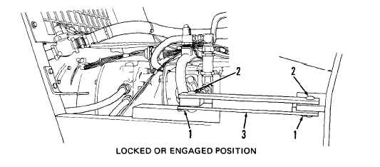
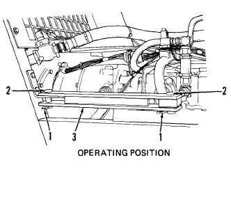
d. T r a n s p o r t / S e r v i c e L i n k.
This task covers locking, removal, and installation
of the transport/service link. In locked or engaged position, the loader is
prevented from pivoting or turning. This link should be in the locked or engaged
position whenever you are servicing loader in area between front and rear chassis.
TOOLS: No. 1 Common Organizational Maintenance Tool Kit
S l i p j o i n t p l i e rs
LOCKING OR ENGAGING TRANSPORT/SERVICE LINK
(1) At right side of loader, on rear chassis, remove two clip pins (1).
( 2)
Remove two pins (2).
(3) Remove transport/service link (3) and position between center mount and
ear on front chassis .
(4)
Install two pins (2) and secure using two clip pins (1).
UNLOCKING OR DISENGAGING TRANSPORT/SERVICE LINK
(1)
( 2)
(3)
(4)
At right side of loader, on
front chassis, remove two clip
p i n s ( l ) .
Remove two pins (2).
Remove transport/service link
(3) and position between center
mount and ear on rear chassis.
Install two pins (2) and secure
using two clip pins (1).
9-8


