TM 5-3805-262-34
4-5. STEERING CYLINDER ASSEMBLIES MAINTENANCE (CONT)
REASSEMBLY (SHEET 4 OF 4)
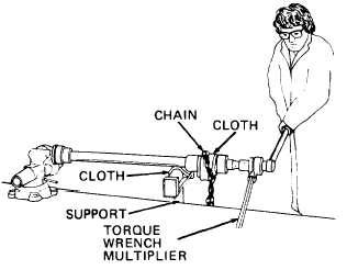
1. Install washer (3) and capscrew (2)
on rod (7). Tighten capscrew to 380
to 450 lb-ft. Use torque wrench
multiplier and a chain to hold rod
stationary. Put cloth between chain
and rod to prevent damaging rod.
In following step, do not
over-tighten vise. Over-
tightening will distort
cylinder tube (24).
m. Put cylinder tube (24) in vise.
n. Lubricate cylinder tube (24) inside wall and piston assembly (17 thru 20)
using clean lubricating oil.
o. Install rod (7) with gland and piston assemblies in cylinder tube (24) as
follows:
(1)
Start rod (7) into cylinder tube (24).
(2)
Screw gland assembly (8 thru 16) into cylinder tube (24). Do not tighten.
(3) Push rod (7) farther into cylinder tube (24) using soft hammer or steel
rod inserted through rod (7) eye.
p.
q.
r.
s.
4-248
NOTE
If gland (16) has a plug (12) go to step p below. If gland (16) and
cylinder tube
(24) use screw (1) go to step q. If same gland is
installed that was removed or if a new gland is installed go to step r.
Install gland (16) into cylinder tube until gland comes in contact with cylin-
der tube. Using spanner wrench, tighten gland to 200 to 300 lb-ft.
Tighten gland (16) to 100 to 200 lb-ft. Each half of hole for screw (1) must
be alined. Install screw (1). If each half of hole is alined before 100 lb-ft
torque, drill a new hole half in gland and half in tube. Use number 26 drill
bit and drill 5/16 inch deep. Don’t drill hole in same position as a hole for
spanner wrench. Install screw (1).
Tighten gland (16) to 100 to 200 lb-ft. Drill a hole half in gland and half in
tube. Use number
same position as
Install steering
26 drill bit and drill 5/16 inch deep. Don’t drill hole in
a hole for spanner wrench. Install screw (1).
cylinders (page 3-564).