TM 5-3805-262-34
4-6. CHASSIS SPINDLE ASSEMBLY MAINTENANCE (CONT)
REMOVAL (SHEET 2 OF 2)
e.
f.
g.
h.
i.
j.
k.
l.
m.
n.
Remove 6 capscrews (1) and lock washers (2) from upper chassis spindle (3).
Install two capscrews in threaded puller holes in spindle (3). Tighten cap-
screws evenly to pull spindle (3) from rear chassis.
Remove spindle (3), thrust bearing (4), and O-ring (5). Discard O-ring.
Remove lubrication fitting (7) from upper thrust plate cap (8).
Loosen and remove five capscrews (1) and lock washers (2) from upper thrust
plate cap (8).
Hold upper thrust plate cap (8) in position and remove remaining capscrew (1)
and lock washer (2).
Remove upper thrust plate cap (8) and, if present, shims (9 thru 11). Wire
shims together and identify to prevent mixing them with shims from lower
thrust plate cap.
NOTE
Do not perform steps 1 through n below unless inspection indicates parts
replacement is necessary.
Spindle bores in front and rear chassis must be alined to perform steps
l and m below.
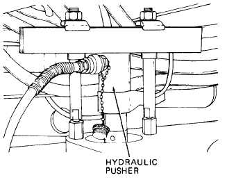
Install suitable hydraulic pusher on
top of rear chassis and push thrust
bearing (6) from bushing (12) using
3-7/8 inches diameter sleeve or rod.
Using 4-1/4 inches outside diameter
sleeve or rod and hydraulic pusher,
push bushing (12) from front
chassis.
Using puller, remove thrust bearing
(4) from spindle (3).
NOTE
Repeat steps e through n above
to remove lower chassis spindle
parts.
4-252