TM 5-3805-262-34
3-7. TRANSMISSION MAINTENANCE (CONT)
c. Transmission Replacement (Cont).
(2) Detailed Procedure (Cont).
INSTALLATION (SHEET 2 OF 3)
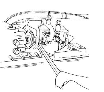
(c) Using a pry bar, raise hydraulic
pump. Move transmission toward
front of loader. Engage hydrau-
lic pump drive shaft with trans-
mission charging pump drive.
Start hydraulic pump mounting
capscrews into transmission.
(d) Aline transmission mounting
holes with associated holes in
bracket (10) by raising or low-
ering transmission as necessary.
(e) Install four lock washers (5),
capscrew (4) and three capscrews
(3). Two inches long capscrew
(4) is installed in top front
mounting hole. Tighten capscrews
to 135 to 165 lb-ft.
(f) Put transmission right side bracket (8) on frame. Install and tighten
washer (7), capscrew (6), washer (2), and new lock nut (l).
(g) Aline transmission mounting holes with associated holes in bracket (8).
Install four washers (5), capscrew (4), and three capscrews (3). TWO
inches long capscrew (4) is installed in top front mounting hole. Tight-
en capscrews to 135 to 165 lb-ft.
(h) Tighten nuts (1) to 135 to 165 lb-ft.
(i) Disconnect chain hoist and transmission jack from transmission.
(j) Install rear drive shaft and connect center drive shaft to transmission
(refer to TM 5-2805-262-20).
(k) Connect parking brake lever to parking brake chamber and adjust linkage
(refer to TM 5-3805-262-20) if necessary.
(l) Position hydraulic system manifold bracket on transmission front cover;
install and tighten capscrew to secure (refer to TM 5-3805-262-20).
(m) Position transmission control cable bracket on transmission; install and
tighten capscrews to secure (refer to TM 5-3805-262-20).
3-338