TM 5-3805-262-34
REASSEMBLY (SHEET 4 OF 4)
(y)
(z)
(aa)
(ab)
(ac)
(ad)
(ae)
(af)
(ag)
(ah)
Position new gasket (7) on crankcase (30).
Install cylinder block assembly (2 thru 18) on crankcase (30).
Install six capscrews (1). Tighten center capscrews first. Then tighten
alternate capscrews to 120-160 lb-in until all capscrews are tight.
Install new insert (10) in
front connecting rod cap
(9). Make sure tab on in-
sert is engaged in notch on
connecting rod cap.
Lubricate inserts (10) and
journals on crankshaft (27)
with clean lubricating oil.
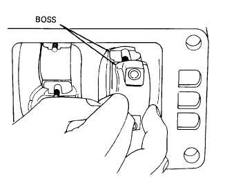
Install front connecting rod
cap (9) on front connecting
rod (12), making sure boss
on connecting rod is aligned
with boss on connecting rod
cap.
Install two capscrews (11) and lock nuts (8). Tighten lock nuts to 100
to 140 lb-in.
Repeat steps (ah) through (se) above for rear connecting rod assembly (8
thru 12).
Install new gasket (6), inlet port
screws (3) on cylinder head (2).
Install cylinder head and unloader
(5), two lock washers (4), and cap-
(page 3-472).
3-493