TM 5-3805-262-34
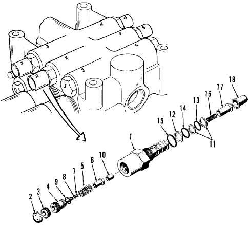
DISASSEMBLY (SHEET 2 OF 2)
NOTE
In following step, record number of turns required to remove adjusting
screw (4).
(8)
Remove adjusting screw (4) with spring (5) and plunger (6). Record number
of turns required to remove adjusting screw. Separate adjusting screw,
plunger, and spring.
(9) Remove two O-rings (7 and 9) and backup ring (8) from adjusting screw
(4). Discard O-rings and backup ring.
(10) Remove seat (10) from body (1) only if necessary for replacement.
(11) Remove three backup rings (11 and 12) and O-rings (13 thru 15) from body
(1). Discard backup rings and O-rings.
(12) Remove spring (16) and poppet (17) from control valve body.
(13) Remove seat (18) from control valve body only if necessary for replace-
ment.
LEGEND
1. Body
2. Expansion plug
3. Plug
4. Adjusting screw
5. Spring
6. Plunger
7. O-ring
8. Backup ring
9. O-ring
10. Seat
11. Backup rings (2)
12. Backup ring
13. O-ring
14. O-ring
15. O-ring
16. Spring
17. Poppet
18. Seat
3-699