TM 5-3805-262-34
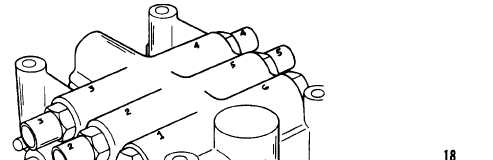
3-22. CONTROL VALVE ASSEMBLY MAINTENANCE (CONT)
g. Circuit Relief Valves (Cont).
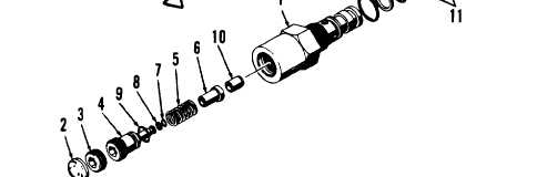
REASSEMBLY (SHEET 2 OF 2)
NOTE
Do not install plugs (2 and 3) until
setting has been adjusted.
(7) Remove body (1) from vise. Install
three new backup rings (11 and 12)
(8) Install seat (18) in control valve
circuit relief valve pressure
three new O-rings (13 thru 15) and
on body (1).
body if removed.
(9)
Install poppet (17) and spring (16) in control valve body.
(10) Lubricate O-rings (13 thru 15) and control valve body bore using clean
lubricating oil.
(11) Install body (1) in control valve body and tighten.
(12) Adjust circuit relief valve (page 3-703) .
LEGEND
1. Body
2. Expansion plug
3. Plug
4. Adjusting screw
5. Spring
6. Plunger
7. O-ring
8. Backup ring
9. O-ring
10. Seat
11. Backup rings (2)
12. Backup ring
13. O-ring
14. O-ring
15. O-ring
16. Spring
17. Poppet
18. Seat
3-702