TM 5-3805-262-34
REASSEMBLY (SHEET 3 OF 3)
v.
w.
x.
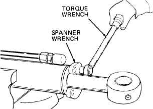
Tighten gland (14) to 100 to 200
lb-ft. Each half of hole for screw
(1) must be alined. Install screw
(1). If each half of hole is alined
before 100 lb-ft torque, drill a new
hole half in gland and half in tube.
Use number 26 drill bit and drill
5/16 inch deep. Don’t drill hole in
same position as a hole for spanner
wrench. Install screw (1).
Tighten gland (14) to 100 to 200
lb-ft. Drill a hole half in gland and
half in tube. Use number 26 drill bit
and drill 5/16 inch deep. Don't drill
hole in same position as a hole for
spanner wrench. Install screw (1).
Install lift cylinder assemblies (refer to TM 5-3805-262-20).
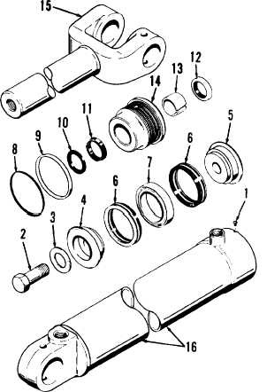
LEGEND
1. Screw
2. Capscrew
3. Washer
4. Piston
5. Piston
6. Packing assemblies (2)
7. Ring
8. O-ring
9. Backup ring
10. Seal
11. Seal
12. Wiper
13. Bushing
14. Gland
15. Rod
16. Cylinder tube
3-743