
TM 5-3805-290-23-1
ELECTRICAL SYSTEM TESTS, INSPECTIONS, AND ADJUSTMENTS - CONTINUED
0013 00
DIGITAL THROTTLE POSITION SENSOR CIRCUIT TEST - CONTINUED
1.
Check for connector damage.
427-B0687
a.
Turn engine start switch to OFF position (TM 5-3805-290-10).
b.
Disconnect engine ECM and throttle position sensor wiring harnesses (WP 0039 00 and WP 0053 00).
c.
Check connectors and wiring for these problems: damage, abrasion, corrosion, and incorrect attachment.
d.
Refer to Electrical Connectors Inspection (WP 0022 00), as necessary.
e.
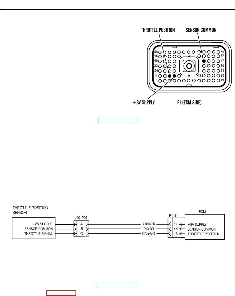
Perform 10 lb (45 N) pull test on each wire in ECM connector associated with pedal-mounted throttle position sen-
sor:
(1)
P1:16
(2)
P1:17
(3)
P1:44
f.
Connect engine ECM and throttle position sensor (WP 0039 00 and WP 0053 00).
g.
Check ECM connector (socket-head screw) for proper torque of 55 lb-in. (6 Nm).
427-B0688
h.
Expected Results. Connectors and wiring should be free of these problems: damage, abrasion, corrosion, and incor-
rect attachment.
(1)
If connectors and wiring are OK, proceed to step 2.
(2)
If connectors and wiring are NOT OK, replace wiring harness in question (WP 0169 00 thru WP 0175 00).
2.
Check for active diagnostic codes.
a.
Turn engine start switch to ON position (TM 5-3805-290-10).
b.
Connect MSD (WP 0006 00).
c.
Use MSD to check for diagnostic codes.
0013 00-21